Reactor Vessel Head Degradation - Images
On this page:
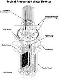
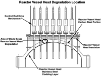
Reactor Pressure Vessel Top Head Images
 |
 |
| See the following for a larger version of the above image or | See the following for a larger version of the above image or |
Overview of the Davis Besse Reactor Head Inspection Area
Looking Down at the Davis Besse Reactor Head Inspection Area
Looking Down (second angle) at the Davis Besse Reactor Head Inspection Area
Looking Up at the Davis Besse Reactor Head Inspection Area
Underneath the Davis Besse Reactor Head
Davis Besse Control Rod Drive Open Access Hatch View
Davis Besse Reactor Vessel Head Insulation Top View with Nozzle #3 Removed
Davis Besse Reactor Vessel Head Insulation Top View with Nozzle #3 Removed (overhead view)
Degradation Area of Davis Besse Nozzle #2
Degradation Area of Davis Besse Nozzle #3
Degradation Area of Davis Besse Nozzle #3 Sketch
Cavity Looking Toward Nozzle Eleven
Closeup View of Cavity Looking Toward Nozzle Eleven
Containment Access Location
Underneath View of Cutout
Underneath View of Cutout - Closeup View
17 Inch Cutout - View 1
17 Inch Cutout - View 2
Downward View of Reactor Vessel Head Cutout Hole - View 1
Downward View of Reactor Vessel Head Cutout Hole - View 2
Downward View of Reactor Vessel Head Cutout Hole - View 3
Looking Back Toward Nozzle Three
Looking Toward Nozzle Eleven
Nozzle Eleven Perspective
Undercut Area Toward Nozzle Eleven
Transporting New Head to Davis Besse
Top View of Cladding
Crack in Cladding
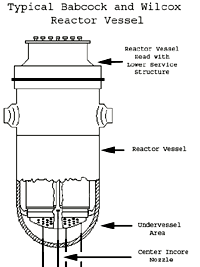
Reactor Pressure Vessel Bottom Head Images
 |
| See the following for a larger version of the above image |
Undervessel Pre-Cleaning Center Incore Nozzel - View 1
Undervessel Pre-Cleaning - View 2
Undervessel Post-Cleaning - View 3
Page Last Reviewed/Updated Tuesday, November 03, 2020
Page Last Reviewed/Updated Tuesday, November 03, 2020

