Resolution of Generic Safety Issues: Issue 193: BWR ECCS Suction Concerns Description ( NUREG-0933, Main Report with Supplements 1–35 )

In order to export or print, this web site requires you to enter text displayed in the distorted image on the left, which is known as Captcha, into the text field below the image.
DESCRIPTION
Historical Background
This issue was identified1814, 1815 by a Region III inspector and addressed the possible failure of low pressure emergency core cooling systems due to unanticipated, large quantities of entrained gas in the suction piping from suppression pools in BWR Mark I containments.
Safety Significance
Three specific concerns were listed in the identifying document:1814
- One of the bounding design basis accidents is a LOOP combined with a LOCA. While this may be bounding from an ECCS performance perspective, it may not be bounding from a gas entrainment perspective. Because the pumps may start sooner during a LOCA without a LOOP, bubbles generated during the initial blowdown may not have risen to the surface and more may become entrained in the ECCS suction piping. Since a LOCA without a LOOP was not considered, this aspect should be considered for further evaluation.
- An AEOD evaluation1817 of potential air binding or performance degradation of RHR pumps only used the volume of water in the RHR suction piping to determine the amount of dissolved gas. However, the amount of gas that is potentially available to affect pump performance is the total volume of water in the suction piping and the suppression pool. The potential for pump air binding or performance degradation may need to consider the total volume of available water in determining the volume of gas.
- The swell/exclusion zone in the torus after a LOCA is considered to be limited to less than one diameter of the downcomer pipe. There does not appear to be a technical basis for this limitation, and it may not be conservative. The intrusion of non-condensable gas into the torus may be greater and the effect will potentially be worse due to the larger suction strainers installed in response to NRC Bulletin 96-03.1816 Adequate bases to limit the exclusion zone to less than one diameter of the downcomer pipe should be established, especially with respect to the recently installed larger suction strainers.
Possible Solution
There are several possible solutions to this potential problem. One alternative would be to install a sensor at the ECCS pump suctions, and inhibit either pump startup or discharge valve opening until a stable liquid-phase flow supply is verified. Another approach would be to change the sequencing of the pumps onto their individual buses during ECCS startup. Still another would be to line up one of the ECCS train suctions to the condensate storage tank or other alternative water source. In addition to the above, the installation of anti-vortexing devices to the ECCS suction strainers might be necessary.
It is not clear at this point which solution would be practical or cost-effective. However, because of the fast timing of the event in question, it is likely that the "fix" will involve some hardware modifications to the plant, and not be just procedural.
SCREENING ANALYSIS
Background
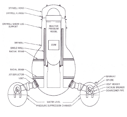
Figure 3.193-1
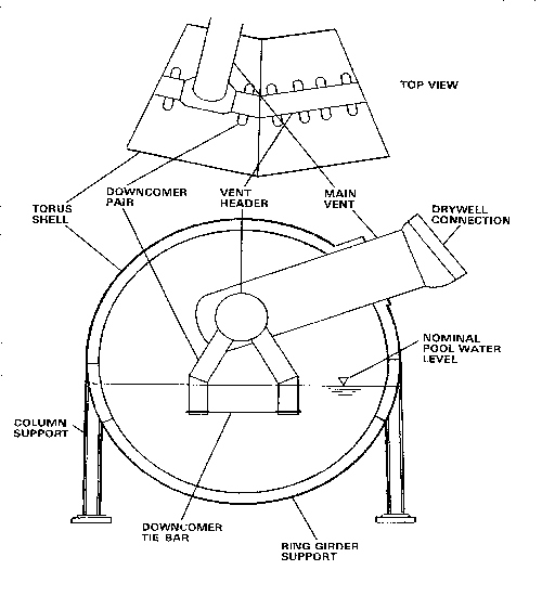
Figure 3.193-2
ASSESSMENT
Pressure Suppression Design: The pressure suppression chamber, or torus, in a BWR Mark I containment, is a steel pressure vessel in the shape of a torus below and encircling the primary containment drywell, which contains the reactor vessel and recirculation system pumps and piping (Figure 3.193-1). In the event of a LOCA, steam released into the drywell airspace is forced through (typically) eight large vent pipes to the suppression chamber. The vent pipes exhaust into a large ring-shaped continuous vent header within the torus. The header is connected to a set of downcomer pipes, which extend into the suppression pool water, and end about four feet below the water surface (Figure 3.193-2). The steam is condensed in the suppression pool water, greatly limiting the peak containment pressure.
BWR Mark I containments operate with the containment atmosphere "inerted," i.e., with less that 4% oxygen by volume. Thus, in the text than follows, the term "air" generally refers to this containment atmosphere composition.
Dynamic Effects of Pressure Suppression: The dynamic effects of a primary system blowdown on the suppression chamber and pool have been studied rather extensively in the Mark I containment short-term and long-term programs (see Issue A-7, "Mark I Long-Term Program"). The primary thrust of this program was the evaluation of the loads (forces exerted) on the containment structure and components, not the effects of entrained non-condensible gases on the ECCS suction. Nevertheless, the phenomena are the same. The effects of the blowdown are well-described in NUREG-0661,702 portions of which are quoted here:
"With the instantaneous rupture of a steam or recirculation line, a shock wave exits the broken primary system pipe and expands into the drywell atmosphere. At the break exit point, the wave amplitude theoretically is equal to reactor operating pressure (1000 psia); however, there would be rapid attenuation as the wave front expands spherically outward into the drywell. Further attenuation would occur as the wave enters the drywell vent system and progresses into the suppression pool.
"Because there would be a very rapid drywell pressure increase associated with the postulated LOCA, a compression wave would propagate into the water initially standing in the downcomers. Before this water is cleared from the downcomers, this compression wave would propagate through the suppression pool and result in a dynamic loading on the suppression chamber (torus). The compression wave could also result in a dynamic loading condition on any structures within the suppression pool.
"With the drywell pressure increase, the water initially standing in the downcomers accelerates into the pool, and the downcomers clear of water. During this water-clearing process, a water jet forms in the suppression pool, and causes a potential water-jet-impingement load on the structures within the suppression pool and on the torus section beneath the downcomers.
"Immediately following downcomer clearing, a bubble of [inerted] air starts to form at the exit of the downcomers. As the bubble forms, its pressure is nearly equal to the drywell pressure at the time of downcomer clearing. The bubble pressure is transmitted through the suppression pool water and results in a downward load on the torus.
"When the air/steam flow from the drywell becomes established in the vent system, the initial bubble expands and subsequently decompresses as a result of over-expansion. During the early stages of this process, the pool will swell in bulk mode (i.e., a ligament of solid water is being accelerated upward by the air bubble). During this phase of pool swell, structures close to the pool surface experience impact loads as the rising pool surface strikes the lower surfaces of the structures. This is followed by drag loads as the pool surface continues to rise past the structures. In addition to this impact and drag loads above the pool, there will also be drag loads as the bubble formation causes water flow past submerged structures and equipment.
"As the water slug continues to rise (pool swell), the bubble pressure falls below the torus airspace pressure. However, the momentum of the water slug causes it to continue to rise, this compresses the air volume above the pool and results in a net upward pressure loading on the torus. The thickness of the water slug will decrease as it rises. Aided by impact of the vent header, it will begin to break up and evolve into a two-phase "froth" of air and water. The froth will continue to rise of its own momentum, and it will impinge on structures above the pool breakthrough elevation.
"When the drywell air flow rate through the vent system decreases and the air/water mixture in the suppression pool experiences gravity-induced phase separation, the pool liquid upward movement stops, and the "fallback" process starts. During this process, structures in the torus may experience a downward loading, and the submerged portion of the torus could be subjected to a pressure increase. Following "fallback," waves may develop on the suppression pool surface, thereby presenting a potential source of dynamic loads on the downcomers, torus, and any other structures close to the water surface.
"The pool swell transient typically lasts on the order of 3 to 5 seconds. Because of the configuration of the pool, this period is dominated by the flow of the drywell atmosphere through the vent system. Steam flow will follow, beginning near the end of the pool swell transient, with a relatively high concentration of noncondensible gases. Throughout these periods, there is a significant pressure differential between the drywell and the torus. This, together with flow-induced reaction forces, leads to structural loads on the vent system."
It is common for BWRs with a MARK I containment to maintain a slight differential pressure between the drywell and the suppression pool airspace, to depress the water level in the downcomers and reduce the hydrodynamic forces caused by expelling a vertical column of water downward from the downcomer exits - the water level is maintained just above the end of the downward-leading pipes. This will reduce the hydrodynamic drag loads, but not the quantity of entrained air.
Thus, it seems reasonable to conclude that the blowdown of the primary system through the drywell and through the suppression pool is a rather violent process. Even though the suction header is somewhat protected from what is occurring within the torus itself, the originator of this issue has posed a reasonable question: will a significant amount of entrained containment atmosphere be sucked into the various ECCS pumps? Clearly, this is a question of timing, since the blowdown phenomena are transient, and the pool will eventually settle down.
Dissolved Gas: The originator of the issue also mentioned potential air binding or performance degradation of RHR pumps due to dissolved gas. This phenomenon was investigated by AEOD in 1982.1817 Because the suppression pool water is in equilibrium with the airspace above it, there is always some gas (primarily nitrogen) dissolved in the water. When this water quenches the steam from a primary system blowdown, the water heats up. As the water temperature rises, the solubility of gases decreases, and the dissolved gas comes out of solution and is liberated into its gaseous state. The experiments indicated that the gas was released in the form of a vast number of very small bubbles, less than one millimeter in diameter. Such small bubbles do not rise rapidly to the surface, and could be drawn into the ECCS suction piping.
ECCS System Timing: To see the effects of entrained gas, as postulated by this issue, it is necessary to review ECCS system timing. The details of ECCS initiation can vary from plant to plant. The description used here is based on Browns Ferry 1. Although this plant has been shut down for some time, it was used for many years as the basis for NRC training classes and, for this reason, its design details are readily available. The ECCS pump configuration and the details of the onsite and offsite power systems can vary significantly from plant to plant.
The originator of the issue stated1814 the difference between ECCS initiation with offsite power available and ECCS initiation when the emergency diesel generators must be used. A diesel generator will always be wired to auto-start on loss of voltage on its associated 4160-Volt shutdown board. Thus, if a LOCA were caused by a seismic event, it is likely that the diesels will already be running when the LOCA occurs, since the same seismic event is likely to damage the transmission lines and cause a loss of offsite power.
In addition, there is an anticipatory diesel generator start signal which is generated be either a combination of high drywell pressure and "low" reactor vessel pressure, or by "low-low-low" reactor water level (by itself). The diesel generators are capable of accepting load within 10 seconds of receiving the automatic start signal. Once each diesel generator is ready, if voltage on its associated shutdown board is low or lost, the diesel generator will be connected to the board. If voltage is normal on the shutdown board, the diesel generator will continue to run at rated speed and voltage, immediately available to be connected.
There are two low pressure ECCS systems in BWRs from the BWR/3 design on. Each of these systems meets the single failure criterion. One is the LPCI mode of the RHR system. LPCI is a high volume reflooding system which injects emergency coolant into the recirculation pump discharge pipes. The flow is then directed into the jet pump nozzles and thus to the lower plenum, which eventually refills and floods the reactor core from the bottom. The other is the low pressure core spray, which has a lower flow capacity but injects water to a pair of spargers located within the reactor vessel core shroud above the core. This flow then sprays down directly into the core from above.
The low pressure ECCS system initiation sequences have several steps. (This can vary from plant to plant, but the example of Browns Ferry will be used here.) For LPCI, the pumps start on either low-low-low reactor water level or on high drywell pressure combined with low reactor vessel pressure. Upon receipt of the start signal, the response depends on the availability of power. If normal AC power is not available, the four main RHR pumps are started essentially simultaneously, as soon as the diesel generators are capable of taking load - about 10 seconds after diesel start, if the diesels are not already running. In contrast, if normal AC power is available, the four pumps start in a seven-second timed sequence, to prevent overloading the auxiliary power source. In either case, it takes time for the pumps to get up to speed. Meanwhile, once reactor pressure has decreased to below 450 psig, which will take about 24 seconds, the inboard LPCI injection valves will automatically open. As reactor pressure continues to fall to 230 psig, the recirculation pump discharge valves are signaled to close, to direct flow to the jet pumps and thereby to the lower plenum of the reactor vessel. Flow will not begin until the pressure in the reactor vessel drops below the discharge pressure of the RHR pumps, which will take about 30 seconds, and will not reach full value until the recirculation pump discharge valves fully close, which will take approximately 30 seconds more.
Similarly, the low pressure core spray pumps start on either low-low-low reactor water level or on high drywell pressure combined with low reactor vessel pressure. If offsite power is available, the pumps are started in a seven-second timed sequence, just as are the LPCI pumps. If offsite power is not available, and the boards are powered by the diesel generators, the core spray pumps are started together, but seven seconds after power is available, so that they do not start at the same time as the LPCI pumps. Once reactor vessel pressure drops to 450 psig, the pump discharge valves open, allowing water to be sprayed over the core. Table 3.193-1, taken from the training manual, summarizes the operational sequence for a large break LOCA with no offsite power available.
Table 3.193-1
Fast Sequencing Scenario
| Event | Time (seconds) |
|---|---|
| Design basis LOCA starts | 0 |
| Drywell high pressure and reactor low-low water level | ~1 |
| Scram, design-basis analysis assumes diesel-generators signaled to start, primary containment isolates, recirculation pumps trip | 3 |
| Low-low-low reactor water level. | ~6-8 |
| Diesel generators ready for load/If offsite power not available, start LPCI pumps. | 13 |
| LPCI pumps at speed. Signal all 4 core spray pumps to start | 20 |
| Reactor reaches 450 psig/Core spray and LPCI injection valves signaled to open | 22 |
| Core spray pumps at speed | 25 |
| Reactor reaches 230 psig/Signal recirculation pump discharge valves to close | 26 |
| Recirculation pump discharge valves begin to close | 29 |
| Core spray injection valves fully open | 30 |
| LPCI injection valves fully open | 46 |
| Recirculation pump discharge valves fully closed | 62 |
| Core effectively flooded | ~108 |
If the diesel generators are already running, the LPCI pumps will start at low-low-low reactor water level, and the core spray pumps will start seven seconds later.
A similar table (Table 3.193-2) can be constructed for the situation where offsite power is available, and the diesel generators remain in standby. In this case, the four LPCI pumps and the four core spray pumps are sequenced on in four seven-second intervals, one LPCI pump and one core spray pump at a time.
Table 3.193-2
Slow Sequencing Scenario
| Event | Time (seconds) |
|---|---|
| Design basis LOCA starts | 0 |
| Drywell high pressure and reactor low-low water level | ~1 |
| Scram, Diesel-generators signaled to start, primary containment isolates, recirculation pumps trip | 3 |
| Low-low-low reactor water level/First LPCI and core spray pumps auto start | ~6-8 |
| Second LPCI and core spray pumps auto start | 13 |
| Third LPCI and core spray pumps auto start | 20 |
| Reactor reaches 450 psig/Core spray and LPCI injection valves signaled to open | 22 |
| Reactor reaches 230 psig/Signal recirculation pump discharge valves to close | 26 |
| Fourth LPCI and core spray pumps auto start | 27 |
| Recirculation pump discharge valves begin to close | 29 |
| Core spray injection valves fully open | 30 |
| LPCI injection valves fully open | 46 |
| Recirculation pump discharge valves fully closed | 62 |
| Core effectively flooded | ~108 |
The plant designer has some freedom in low pressure ECCS initiation timing in that there will be no flow into the reactor vessel until the vessel pressure drops to below the shutoff head of the ECCS pumps. Thus, the pump sequencing is not critical so long as all pumps are ready by the time the vessel pressure drops sufficiently to allow injection. The designer will generally design the initiation sequencing to limit the severity of the loading transient on the power supply boards. Although individual plants will vary, the two sequencing schemes described above should bound most designs.
Effect of Concerns: The first of the three concerns asserted that, with normal AC power available, the low pressure ECCS pumps would start earlier, and under such circumstances a significant quantity of entrained gas might be drawn into the pump suctions. As can be seen from the description above, this is not necessarily true - at least in the Browns Ferry example, the pumps are actually sequenced on faster when the diesel generators are supplying power.
However, the overall concern raised by this issue appears to be well taken, regardless of this detail. According to the MARK I Long-Term Program, the pool swell transient typically lasts on the order of 3 to 5 seconds. Some of the LPCI and Core Spray pumps will be signaled to start at 6 to 8 seconds after the start of the accident - very close to this same time frame. Although there will be relatively little flow when the pumps first start, the pump discharge valves will be opening about 22 seconds into the accident, and flow will increase rapidly thereafter.
The second of the three concerns asserted that the original AEOD evaluation1817 calculated only the dissolved gas in the pump suction piping and should have included the entire suppression pool water inventory. It is certainly true that the entire inventory will be subjected to significant heating, and would be expected to release any dissolved gas. However, the amount of gas released into each cubic foot of water will be the same - if the bubbles remain suspended uniformly in the water, the amount of gas entering a pump suction with each cubic foot of water will not change. Most will be released in the initial heatup, as the reactor blows down. Eventually, these gas bubbles will concentrate and coalesce, but they are unlikely to do so in a downward direction. Moreover, the AEOD report1817 concluded that the pumps were able to tolerate the 2% (by volume) air content "without a discernable loss in pump performance." There is no new information presented to invalidate this conclusion, but this source of entrained gas will be included in the analysis.
The third concern has to do with the swell exclusion zone (basically how large an area is affected by the blowdown through one of the downcomers) and the sizing of the suction strainers. The concern appears to be that the initial bubble formed during the air-clearing phase will extend to the 30-inch connecting tee, and gas rather than liquid will be drawn into the pipe. This can happen for two reasons. First, when the pumps are running, there will of course be flow into the suction piping. However, the pumps are likely running on minimum flow (if they have started at all) during the air-clearing phase of the transient, and the bubble drawn into the suction piping due to this reason would be limited in size. Second, the force of the blowdown could force some non-condensible gas directly into the suction piping, independent of any flow caused by pump operation.
Given the violent nature of the blowdown into the suppression pool, the first and third concerns do have some credibility. The basic questions are first, whether the design of the ECCS suction configuration will be able to keep significant quantities of entrained gas away from the various pump inlets, and second, whether the pool will have sufficiently settled down by the time the pumps are delivering significant flow.
Specifically, at least some of the pumps will be starting just as the air-clearing phase of the blowdown has most of the suppression pool "on the ceiling." The pump flow will just be that of the minimum flow lines (about 500 gpm) which return flow back to the suppression pool. The pumps require about 30 elevation feet of water (about 13 psi) for NPSH, which should not be a problem, since the blowdown will pressurize the suppression chamber to at least this level. However, if large air bubbles are drawn into such a pump, the result will be air binding, flow instability, high vibration, and ultimately impeller damage if the pump does not trip on high vibration or on electrical supply current instability.
Frequency Estimate
The design basis event for the large break ECCS is, as the originator of this issue stated, a large-break LOCA combined with a LOOP, plus an assumption of worst-case single failure. As was discussed above, there is some question as to whether the case with offsite power or the case without offsite power is the more limiting for this issue. Both will be considered.
Initiating Event Frequency: For the case where offsite power is available, the initiating event is a large break LOCA. Instead of using the "traditional" NUREG-11501081 value of 10-4 event/RY, a more modern value of 3 x 10⁻⁵ event/RY, based on the analysis of operating experience, will be used. (See Appendix J of Reference 1819) However, the effect of this choice will be explored with a sensitivity study - this is not intended as an endorsement of the more modern estimate. (Further discussion can be found in the "Other Considerations" below.)
The case where offsite power is not available (the design basis) is somewhat more complicated. The random likelihood of a large LOCA occurring simultaneously with a LOOP is very small, and the probability of a LOOP subsequent to a LOCA is relatively low. The probability value used in the Peach Bottom PRA 1081 was 2 x 10⁻⁴ (mean). Combined with the 10-4/RY large LOCA-initiating event frequency in NUREG-1150,1081 the combined LOCA-LOOP event would have a frequency on the order of 10-7/RY or lower. However, a seismic event could cause both a LOOP and a LOCA. (Fire-initiated LOCAs are generally stuck-open SRVs and are not applicable to this issue.)
Such a seismically-induced combined LOCA-LOOP was included in the external events analysis PRA for the Peach Bottom plant.1081 In the Peach Bottom seismically-induced large LOCA, the frequency was computed based on the failure of the supports of the recirculation pumps. (Failures of the piping were not included as a review of their capacities showed that they were significantly higher than the pump support failures, and thus would make a negligible contribution to the initiating event frequency.) However, an earthquake severe enough to topple a recirculation pump can be expected to break the ceramic insulators on the transmission lines, thereby causing a loss of offsite power. (The ceramic insulators' fragility is listed as 0.25g and the lowest ground motion interval considered in the large LOCA analysis is 0.23g.)
To estimate the frequency of a seismically-induced LOCA-LOOP event, the seismic event frequency and consequent large LOCA probability for each ground motion interval were multiplied, and the products summed to get an overall large LOCA frequency. Since the ground motion intervals were all at or above the ceramic insulator fragility, all of these LOCAs are expected to also result in a non-recoverable LOOP. The result was 6 x 10⁻⁵/RY for the LLNL seismic hazard curve and 2.6 x 10⁻⁶/RY for the EPRI seismic hazard curve.1318 Although these estimates differ by about a factor of 20, they will bound most seismic studies. In this analysis, the EPRI curve was used as being more representative of a low seismicity site. The original LLNL curve, which was modified, was used in a sensitivity study below to examine the effect of higher seismicity.
Pump Failure Probability: The parameter of greatest significance for this issue is the probability of pump failure as a function of time after LOCA initiation. This probability can be broken down into two factors: (1) the probability of failure as a function of the volume percent of entrained air in the pump suction; and (2) the fraction of entrained air in the suppression pool volume as a function of time.
The entrained air comes from the three sources discussed earlier. During the initial portion of the blowdown, the drywell atmosphere is carried along with the steam through the downcomers and injected into the suppression pool, until the drywell free volume is essentially all steam and water vapor. Also, the heatup of the suppression pool water will cause some dissolved gas to come out of solution. Finally, during the initial blowdown, the suppression pool water is violently mixed with the air in the upper portion of the torus. Once the blowdown is complete, the water will fall back down relatively rapidly into the lower portion of the torus, but it may take some time for the entrained air bubbles to rise to the surface of the pool.
Although there may be some uncertainty in the amount of non-condensible gas which will be present, the total amount (number of moles) of gas will not have a direct effect on the total void fraction in the suppression chamber free volume. The total free volume is fixed, and the total liquid volume is also fixed since the liquid is essentially incompressible. Therefore, the total volume available to be occupied by air is also fixed. Adding more moles of air will only increase the pressure but not directly effect the total gas volume. (Pressure can cause second order effects, e.g., by driving some air back into solution, but this is not expected to be significant.)
Experimental Work: In the late-1970s, the GE performed a series of experimental tests on a full scale model of a MARK I containment.1818 The test facility was only a portion of a full 360 torus but was otherwise full scale. Two of the tests simulated a large-break LOCA, a large steam break (Test M7), and a large liquid break (Test M8). The objective of these tests was to measure hydrodynamic loads and structural response, not air entrainment, but the tests nevertheless provided some insight for the purposes of this issue.
In these tests, after the initial blowdown, pool swell, and air-clearing, the system eventually reached a fairly stable condition in which steam exiting the downcomer formed a bubble at the downcomer exit, with steam condensing at the surface of the bubble. The situation was stable in the sense that the downcomer exit bubble presumably expanded until the bubble's surface area was sufficient for the rate of condensation at the bubble surface to match the mass flow of steam into the downcomer. (BWRs have TS limits on initial suppression pool temperature that are intended to ensure stable steam condensation after a blowdown.)
Two phenomena were observed in the tests: chugging and condensation oscillations. Chugging occurred during some of the tests simulating small steam breaks, which are not of significance for this issue. However, condensation oscillations, which were generated by the condensation process at the steam bubble surface, continued for an extended period of time and were observed in all tests, including those tests simulating the large steam and liquid breaks. Because of these condensation oscillations, a certain degree of turbulence will be present in the suppression pool throughout an actual LOCA event.
Although the instrumentation and measurements in these tests were geared toward structural impacts, there were some observations that have some significance for this issue. For example, in Test M8, the large liquid break, the weight percent of air was 3% in the south vent line three seconds into the test. By 15 seconds, it had dropped to 0.2%, and by 25 seconds it had dropped to 0.09%. However, at 40 seconds, the weight percent of air went back up to 0.4%. Thus, there is experimental evidence that air injection will continue at a low rate for some time after the pool swell, but the majority of the drywell atmosphere is injected into the pool very early.
Also, some visual observations were made during the tests. These observations were limited in the sense that the condensing vapor in the wetwell airspace tended to obscure the view, but it was noted in the report that the liquid surface exhibited standing waves that appeared to be correlated with the condensation oscillations associated with the downcomers. After the initial pool swell, standing waves of roughly 2 to 3 inches in amplitude were observed after 13 seconds from test initiation for the liquid break, and after 20 seconds for the steam break. Thus, in this time range, the experimental evidence seems to point to an agitated pool, but a pool with a reasonably well-defined surface.
Bubble Rise Phenomena: The GE experimental work did not record the parameters of most interest for this issue, and thus it is necessary to use some more general knowledge of such phenomena. According to the BWR Fundamentals training manual, the height of the suppression pool air and liquid space (i.e., minor diameter of the torus) is typically about 29 feet. After being forcibly thrown up "to the ceiling" by the initial blowdown, the suppression pool water will fall back in about one second, held back only by air drag. However, entrained air bubbles in the pool will take much longer to rise to the surface, because of the viscosity of the water.
Steam bubbles in subcooled water will break up and disperse quite rapidly, and the increased surface area of the smaller bubbles will lead to rapid condensation. Air bubbles, in contrast, may break up or coalesce, depending on size and surroundings, but will persist until they rise to the pool surface.
In theory, air bubbles will rise and achieve a terminal velocity governed by Stoke's law. Although experiments have shown that Stoke's law works reasonably well for individual bubbles small enough (under 2 mm) for the flow around them to be laminar, a number of effects alter the terminal velocity in practice. An extensive discussion of these effects is contained in "Liquid-Gas Systems," (Fair, J.R., Steimeyer, D.E., Penney, W.R., and Brink, J.A., in "Chemical Engineers' Handbook," Perry, R.H., and Chilton, C.H., Fifth Edition, McGraw-Hill, New York, 1973) which include the following:
- At a Reynolds number of about 100, a wobble occurs that causes bubbles to rise in a spiral or helical path.
- Above about 2mm, the bubbles change from spheres to ellipsoids, and above 1 cm, they become lens-shaped.
Both of these effects will tend to lengthen the time bubbles will remain in the suppression pool. In addition, "Liquid-Gas Systems," (Fair, J.R., Steimeyer, D.E., Penney, W.R., and Brink, J.A., in "Chemical Engineers' Handbook," Perry, R.H., and Chilton, C.H., Fifth Edition, McGraw-Hill, New York, 1973) discusses two more effects that occur when bubbles are produced "in clouds" and interact with each other. These two effects actually oppose each other:
- A "chimney" effect can develop in which the cloud of bubbles cause a significant upward current in the middle of the bubble stream, which will accelerate bubble rise.
- The proximity of bubbles to each other will hinder the downward flow of the liquid displaced by the bubbles, which will slow the rate of bubble rise.
Thus, the velocity of bubble rise is not easily calculated from theoretical principles, and empirical data must be used. Considerable experimental data can be found in: (1) Fair, J.R., Steimeyer, D.E., Penney, W.R., and Brink, J.A., "Liquid-Gas Systems," in Perry, R.H., and Chilton, C.H., "Chemical Engineers' Handbook," Fifth Edition, McGraw-Hill, New York, 1973; and (2) Griffith, P., "Two-Phase Flow," in Rohsenow, W.M., Hartnett, J.P, and Gani, E.N., "Handbook of Heat Transfer Fundamentals," McGraw-Hill, New York. However, these references are intended for chemical engineering applications where bubble columns are intentionally designed to produce a large number of small bubbles, to maximize the interfacing surface area over which chemical reactions can occur. For bubble diameters of a few millimeters, these references predict a bubble rise velocity on the order of about 0.8 feet/second. It is unlikely that bubbles in a suppression pool will be quite this small.
However, CEN 420-P, Volume 1,1820 describes experimental work done in support of small break LOCA analyses, which is likely to be a more realistic estimate for a suppression pool situation. This correlation gives a "best" estimate of about 3 feet/second at atmospheric pressure, with the data ranging from about 1.7 to 3.3 feet/second. For purposes of this issue, a best estimate of 3 feet/second will be used, but a sensitivity study will be done to see the effect of a rise velocity as low as 0.8 feet/second.
Effect of Turbulence: Bubble rise experiments are generally performed in still water, which will not be the case for a suppression pool right after the blowdown associated with a large-break LOCA. There will be considerable turbulence caused by condensation oscillations arising from steam condensation at the downcomer exits. This effect is not likely to cause significant change in the bulk bubble rise velocity, since this turbulence is equally likely to force a bubble up or sideways as to force it down, with little net effect. (This turbulence may cause some breakup of larger air bubbles into many smaller bubbles, however.)
However, there are likely to be residual macroscopic "swirling" currents induced by the initial blowdown and collapse of the pool swell, plus significant convection currents induced by the ongoing heating of the pool at the downcomer exits. These currents will force bubbles down in some areas, and up in other areas. The net effect on the rate of bubbles of entrained air being brought to the liquid surface (and thus leaving the liquid volume) will not be great, but these currents will reduce stratification of the bubbles in the pool, keeping the entrained air more well mixed.
Phase Separation: If every air bubble were the same size and rose at the same velocity in still water, the percentage of entrained air would drop linearly to zero at a time equal to the pool depth divided by the velocity of rise. With a pool depth of 14 to 15 feet and a bubble rise velocity of three feet per second, this would be about 5 seconds. If the water were completely still, any calculations based on the entire pool depth would be an overestimate, since the ECCS pumps take suction from the bottom of the pool, not at the pool surface. However, because of the presence of turbulence and currents in the pool, no credit will be taken for such stratification within the pool. Under this assumption, the opposite of completely still water, the bubbles are assumed to remain uniformly mixed in the water volume, and the void fraction can be readily estimated for these conditions.
Consider a pool of irregular shape and depth, with water volume V and surface area A, containing N bubbles rising with velocity v. If the pool is constantly being mixed such that the bubbles remain uniformly distributed over the volume V, the bubble density is then a constant (with respect to position) equal to N/V.
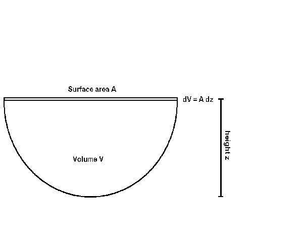
Figure 3.193-3
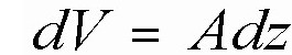
Consider a volume element dV at the surface of the pool, with area A and thickness dz (see Figure 3.193-3).
The number of bubbles in this volume is:
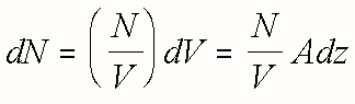
The change in the number of bubbles in the volume V per unit time is:
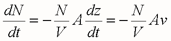
where v is the bubble rise velocity. The integration of this equation is straightforward:
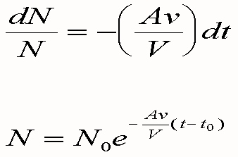
The number of bubbles then follows an exponential decay law, where N0 is the number of bubbles at time t0. Interestingly, the time constant is not directly related to the depth of the pool, but instead is related to the surface to volume ratio and the bubble rise velocity. The semicircular shape of the bottom of a Mark I suppression pool actually contributes to a more rapid loss of air bubbles as compared to a rectangular shape, since there is more surface area per unit volume in a pool with a semicircular bottom.
If the water depth z is approximately equal to the minor radius of the torus, the surface to volume ratio for this horizontal semi-cylindrical shape can be approximated by:
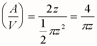
where z is 15 feet. For a relatively simplistic case where all bubbles have the same volume Vb and rise velocity v, the void fraction VF in the pool is:
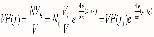
The void fraction then begins at an initial value VF(t0) and drops exponentially with time.
As described above, the bubble rise velocity will be assumed to be 3 feet/second. The pool depth (and torus minor radius) will be assumed to be 15 feet. The "start" time t0 will be assumed to be at the end of the blowdown-induced pool swell, which is 8 seconds. At this time t0, the initial void fraction will be assumed to be 50%, corresponding to the air and water volumes being equal and completely mixed.
This does introduce some conservatism, in that at 50% void fraction, phase separation is due as much to falling droplets as it is to rising bubbles, and the two phases will begin to separate faster than this primitive model would predict, at least for a few seconds. The model's prediction is shown in Figure 3.193-4.
Effect of Entrained Air on Pumps: Cavitation has been cited as one of the most commonly occurring and damaging problems in liquid pump systems (Lobanoff, V.S., and Ross, R.R., "Centrifugal Pumps: Design and Application," Gulf Publishing Co., 1992.). In most nuclear engineering applications, the problem is related to insufficient net positive suction head (NPSH), where the local pressure at the eye of the impeller drops below the vapor pressure of the liquid being pumped, causing bubbles to form. When these bubbles pass through the impeller to a region of higher pressure, where the local pressure is higher than the vapor pressure of the liquid, the bubbles collapse rather violently, creating shock waves in the liquid. Even minor cavitation can produce noise, vibration, loss of head and capacity, and erosion of the impeller and casing surfaces. More severe cavitation can cause cracking of the impeller vanes and pump failure.
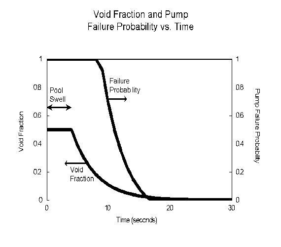
Figure 3.193-4
The specific situation envisioned by this issue is slightly different, in that the cavitation results from entrained air rather than from low pressure. Bubbles formed in this manner will not violently collapse as would bubbles filled with water vapor. In theory, a true "froth" consisting of extremely small bubbles of a non-condensible gas would only have the effect of reducing the density of the pumped liquid, resulting only in some loss of pumping efficiency. However, air bubbles tend to collect at the eye of the impeller, resulting in air binding. In additions, if larger bubbles occur, the result can include turbulence, imbalances in the impeller, severe vibration, and pump failure. A training manual ("Predicting NPSH for Centrifugal Pumps," www.pump.zone.com/articles/00/dec/feature1.htm) quoted by the originator of this issue makes the claim, "A centrifugal pump can handle 0.5% air by volume. At 6% air the results can be disastrous."
Pump Failure Probability: It seems reasonable to assume that the pump failure probability due to entrained air would be essentially unity if the pumps were to be started right at the point of violent pool swell, but that this failure probability contribution would drop fairly rapidly to essentially zero after 20 seconds or so, based on the visual observations in the GE tests. Because the pumps will be starting during this interval, it will be necessary to make some assumptions on how the pump unavailability varies with time.
NUREG/CR-27921821 specifically studied the effect of air and debris ingestion in RHR and containment spray pumps. This study concluded that "for air ingestion level less than about 2%, degradation is not a concern for flows near rated conditions; for ingestion levels in the neighborhood of 5%, performance is dependent on pump design; and for ingestion greater that about 15%, most pumps are fully degraded." It was assumed that the pump failure rate is zero below 2% void fraction, is unity above 15%, and rises linearly from zero to unity between 2% and 15%. This result can be combined with the void fraction estimates described earlier to give a pump failure probability as a function of initiation time, as shown in Figure 3.193-4.
It should be noted that NUREG/CR-27921821 also states that a pump can become air bound at very low flow rates, if operation continues over an extended period of time. Although the pumps will be operating at low flow under the conditions of this issue, this will not be for an extended period of time, and thus the full flow assumptions will be used.
Error Analysis Assumptions: The probability of pump failure due to entrained gas was estimated by using start timing for each group of pumps and inputting this time into the pump failure probability function, as illustrated in the second curve of Figure 3.193-4. In order to perform at least a first effort at an error analysis, the following variations were used:
- The end of pool swell, nominally at 4 seconds, was varied between 3 and 5 seconds, which is the interval given in the literature.
- The bubble rise velocity, nominally three feet per second, was varied between 2.2 and 3.8 feet/second, based on an examination of the data in CEN 420-P.1820
- The pump failure probability curve was varied by shifting entire function such that the "breakpoint" where the failure probability drops to zero moved from a void fraction of 0.02 to a void fraction of zero, and then shifting the function a symmetric amount in the opposite direction. (The rationale was that the failure probability due to entrained gas would have to go to zero at a zero void fraction.)
- The three parameters were each set at their two extremes and failure probabilities for each pump startup time were calculated.
- The resulting ranges at each startup time were assumed to be 95% intervals in a normal distribution.
In addition to this, the effect of bubble rise velocity was also explored with a sensitivity study.
ECCS Failure Probability: The hypothesis of this issue was that the blowdown into the suppression pool is of sufficient severity and duration to cause a loss of NPSH to the LPCI and core spray pumps because of the entrained gas. This would be a common mode failure of the entire low pressure ECCS. The first question is whether the pumps could survive this situation. If the pumps cavitate and the breakers trip, in theory the pumps could be re-started. However, emergency systems are generally not equipped with any more protective trips than are absolutely necessary. Of course, if the pumps are damaged, there will be no recovery. It will be assumed for the purposes of issue screening that a pump will fail and not be recoverable if a significant quantity of entrained gas is drawn into its suction.
For the purposes of this issue, the success criteria used in the PRA1081 for the Peach Bottom plant will be used. Specifically, the success criteria are that either one RHR pump (in LPCI mode) or two core spray pumps will provide sufficient cooling to avoid severe core damage.
As was described earlier, there is more than one possible pump start sequence, depending on specific plant design and depending on whether offsite power is available. The approach will be to use the Browns Ferry sequencing, and then reverse the slow and fast sequences and re-analyze them. This should bound the spectrum of plant designs.
Fast Sequence: An event tree was drawn for the fast sequence, which in the Browns Ferry design corresponds to a LOCA with offsite power unavailable. The initiating event frequency is a seismic event which induces failure of the ceramic insulators on the plant's transmission lines, and also breaks the lateral supports on a recirculation pump. The LOCA is caused by the tipping of the pump.
In this scenario, the diesel generators are likely to be running before the LOCA occurs. All four RHR pumps will start (in LPCI mode) on low-low-low reactor water level six seconds into the accident. All four core spray pumps will start seven seconds later.
Two assumptions are necessary to create an appropriate event tree. First, it is assumed that if a set of pumps does not fail due to entrained gas early in the accident, pumps which are sequenced on later in the transient also do not fail. That is, because the void fraction in the pump suction piping is assumed to be monotonically decreasing, sequences where early pumps do not fail and later pumps do fail are not allowed.
Second, it is assumed that sequences which do not contain at least one pump failure due to entrained gas are not to be included. This is because the parameter of interest for screening generic issues is the change in CDF due to entrained gas. Sequences that lead to core damage but which do not include failures due to entrained gas certainly exist, but are not developed here, since they would be there even if the entrained gas issue were completely fixed.
The event tree for the fast scenario is shown in Figure 3.193-5. (The very first sequence is not developed, since it does not contain any failures due to entrained gas.) The event tree is rather simple in that, if the RHR pumps cavitate, the core spray pumps can fail either due to entrained gas or due to other causes - the "V2" top event in the NUREG-11501081 analysis.
This event tree was analyzed using the SAPHIRE code, using a Monte Carlo analysis of 10,000 samples and an analysis cutoff of 10-10. The results were as follows:
Table 3.193-3
CDF for Fast LOCA Sequences
| Sequence | Point Estimate | Mean | 5th percentile | Median | 95th percentile |
|---|---|---|---|---|---|
| 3 | 2.3 x 10⁻⁹ | 1.4 x 10⁻⁹ | 5.9 x 10⁻¹³ | 5.5 x 10⁻¹¹ | 4.0 x 10⁻⁹ |
| 4 | 6.1 x 10⁻⁷ | 1.3 x 10⁻⁶ | 4.5 x 10⁻¹⁰ | 3.8 x 10⁻⁸ | 2.8 x 10⁻⁶ |
Figure 3.193-5
(Results in Table 3.193-3 and in subsequent tables were given to two significant figures for the convenience of the reader who wishes to follow the calculations, and were not intended to imply that these parameters were known to this accuracy, as the percentile range given in the table itself clearly shows.)
Clearly, this event tree is dominated by sequence number four, where all four LPCI pumps fail due to air entrainment with probability near unity, and the four core spray pumps, which are sequenced on in a group just four seconds later, also fail due to air entrainment with about a 24% probability.
Slow Sequence: The slow sequence corresponds to a LOCA with offsite power available. In this scenario, the pumps are sequenced on in four groups. Each group contains one RHR pump (in LPCI mode) and one core spray pump.
There are two possibilities in this scenario, depending on whether the first RHR pump sequenced to start injects into the intact or into the broken recirculation loop. That is, the pipe break will be in one of the two recirculation loops, and the break will divert injection flow from either RHR pumps 1 and 3, or pumps 2 and 4. (It is assumed that the plant does not use LPCI selection logic.) Because the failure probability due to entrained gas will be different for the four pumps, two event trees were developed, one for each situation.
As in the fast scenario, sequences with no failures due to entrained gas were not developed, and sequences with a successful pump start for an early group but with an entrained gas failure in a later group were not allowed.
Because the four start sequencing groups do not turn on all trains of a system all at once, the event trees are more complex than that of the fast sequence. The two event trees are shown in Figures 3.193-6 and 3.193-7. Because there is no uncertainty in the number of recirculation loops, and both loops are assumed to be identical, the initiating event frequency is one-half the large pipe break frequency for each tree.
Case A is a case where the LPCI pumps that sequence on in Groups 1 and 3 inject into the reactor vessel via the broken recirculation loop. Thus, LPCI trains 1 and 3 are disabled by the LOCA itself, and the accident must be mitigated by either LPCI pump 3, LPCI pump 4, or any two of the four core spray trains. The event tree is shown in Figure 3.193-6. The results were as follows:
Table 3.193-4
CDF for Slow LOCA Sequences (Case A)
These are clearly small numbers, and this sequence is unlikely to be of much significance, at least for this base case. It should be noted that Sequence 11, although low in absolute numbers, is much higher than a hand calculation first indicated. This is because the RHR pump in LPCI Train B and the Core Spray pump in Core Spray Train B are associated with some of the same components in the emergency service water system. If it were not for this common cause failure mechanism, Sequence 11 would be down in the 10-12 range. Also, it should be noted that the underlying PRA models used a cutoff of 10-10 for truncation when building the cut sets, and these numbers are close to this cutoff. Thus, some sequences may be missing, and these numbers may be underestimates. However, because these sequences are of relatively little significance in the total, this should not affect any conclusions.
| Sequence | Point Estimate | Mean | 5th percentile | Median | 95th percentile |
|---|---|---|---|---|---|
| 11 | 1.7 x 10⁻⁹ | 1.3 x 10⁻⁹ | 2.5 x 10⁻¹¹ | 4.1 x 10⁻¹⁰ | 5.1 x 10⁻⁹ |
| 16 | 3.6 X 10⁻¹⁰ | 6.1 x 10⁻¹⁰ | 7.0 x 10⁻¹² | 1.6 x 10⁻¹⁰ | 2.4 x 10⁻⁹ |
Case B is a case where the LPCI pumps that sequence on in Groups 2 and 4 inject into the reactor vessel via the broken recirculation loop. Thus, LPCI trains 2 and 4 are disabled by the LOCA itself, and the accident must be mitigated by either LPCI pump 1, LPCI pump 3, or any two of the four core spray trains. The event tree is shown in Figure 3.193-7. The results for Case B are as follows:
Table 3.193-5
CDF for Slow LOCA Sequences (Case B)
| Sequence | Point Estimate | Mean | 5th percentile | Median | 95th percentile |
|---|---|---|---|---|---|
| 9 | 1.7 x 10⁻⁹ | 1.3 x 10⁻⁹ | 2.5 x 10⁻¹¹ | 4.1 x 10⁻¹⁰ | 5.2 x 10⁻⁹ |
| 13 | 2.7 x 10⁻⁹ | 4.5 x 10⁻⁹ | 2.6 x 10⁻¹¹ | 7.0 x 10⁻¹⁰ | 1.6 x 10⁻⁸ |
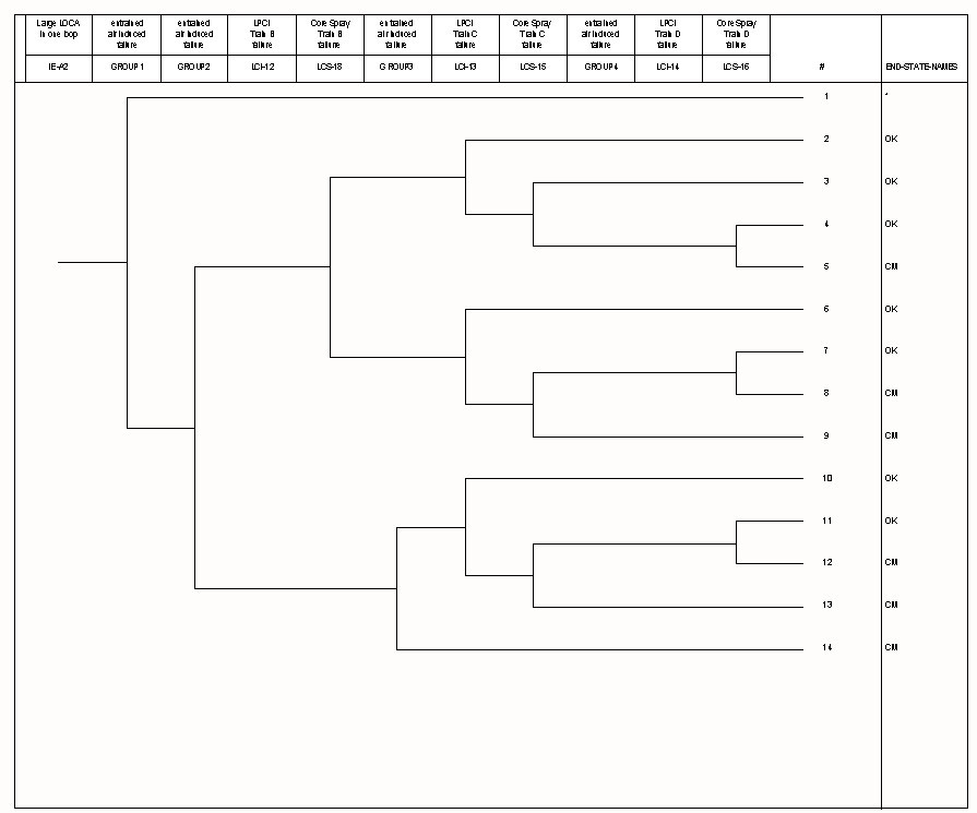
Figure 3.193-6
The numbers are very close to those of Case A. This is primarily because the first few pump groups have failure probabilities of essentially unity, either from gas entrainment or from flow diversion through the broken piping.
Figure 3.193-7
Combined Results, Base Case, Fast and Slow Sequences: The overall results, adding up the two fast sequences and four slow sequences, are as follows:
Table 3.193-6
CDF (Base Case, Total All Sequences)
| Point Estimate | Mean | 5th Percentile | Median | 95th Percentile | |
|---|---|---|---|---|---|
| Combined CDF | 6.2 x 10⁻⁷ | 9.2 x 10⁻⁷ | 2.7 x 10⁻⁹ | 4.7 x 10⁻⁸ | 2.8 x 10⁻⁶ |
Of this total, about 98% is from sequence 4 of the fast LOCA sequence, in which the LPCI pumps are disabled by entrained gas, and seven seconds later the core spray pumps are disabled by entrained gas.
Sensitivity Studies: Four sensitivity studies were performed. All four use the model described above as the base case. The results are tabulated as follows in Table 3.193-7:
Table 3.193-7
CDF (Base Case and Sensitivities)
| Case | Point Estimate | Mean | 5th percentile | Median | 95th percentile |
|---|---|---|---|---|---|
| Base case: Combined CDF | 6.2 x 10⁻⁷ | 9.2 x 10⁻⁷ | 2.7 x 10⁻⁹ | 4.7 x 10⁻⁸ | 2.8 x 10⁻⁶ |
| First case: fast sequencing when offsite power is available | 4.7 x 10⁻⁶ | 8.0 x 10⁻⁶ | 1.2 x 10⁻⁷ | 2.4 x 10⁻⁶ | 3.2 x 10⁻⁵ |
| Second case: high seismicity | 1.4 x 10⁻⁵ | 2.1 x 10⁻⁵ | 1.7 x 10⁻⁸ | 8.7 x 10⁻⁵ | 6.2 x 10 -5 |
| Third case: slow bubble rise | 1.9 x 10⁻⁵ | 1.8 x 10⁻⁵ | 1.6 x 10⁻⁶ | 9.1 x 10⁻⁶ | 5.9 x 10⁻⁵ |
| Fourth case: original LOCA frequency | 6.6 x 10⁻⁷ | 9.9 x 10⁻⁷ | 1.1 x 10⁻⁸ | 1.0 x 10⁻⁷ | 3.0 x 10⁻⁶ |
The first case was done by reversing the initiating event frequencies for the fast and slow sequences, which is equivalent to a plant with pump initiation sequencing that is faster when offsite power is available - the case brought forth originally in this issue. For this case, the mean CDF rises to 8 x 10⁻⁶, almost all of which comes from Sequence 4.
The second case uses the original NUREG-11501081 seismic frequency based on the original LLNL ground motion curve. This case corresponds to a plant wired like Browns Ferry, i.e., where the pumps are sequenced on more rapidly when using the diesel-generators, but located within a high seismic zone. Not surprisingly, over 99% of the CDF again comes from Sequence 4 of the fast LOCA sequence.
The third case uses the base case, but with the bubble rise frequency set to 0.8 feet/second, which corresponds to a suppression pool mixed with very small bubbles - intended to bound the phenomenological aspects of this issue. This case was done to investigate the effect of a slow bubble rise, as would be experienced if the bubbles were all one centimeter or less in diameter. In this case, the pump failure probability is essentially unity except for the fourth group, which has a failure probability of about 65%. (This may not be a physically realistic case, but it does imply that some care should be taken to keep the suppression pool water free of cleaning agents and other surfactants.)
The fourth case was done to illustrate the sensitivity of this model to the spontaneous LOCA frequency. Use of the original LOCA frequency of 10-4/RY instead of the more modern estimate in NUREG/CR-5750,1760 has only a minor effect on the overall CDF. This is because the base case is dominated by the seismic-induced LOCA sequences.
Consequence Estimate
For this issue, all of the sequences that result in severe core damage include failure of all four RHR pumps. These same pumps are also used for suppression pool cooling and for containment spray. Thus, each of these core damage sequences will also result in containment failure due to overpressure.
Cost Estimate
The LERF estimates are such that the cost will not affect the conclusion. Thus, a cost estimate was not performed for this issue.
Other Considerations
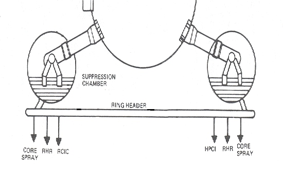
Figure 3.193-8
Effect of Pump Suction Configuration: The analysis assumes that the various LPCI and core spray pumps take suction directly from the suppression pool. The actual suction piping configuration varies from plant to plant. In the case of Browns Ferry, these pumps take suction from a large (typically 30-inch diameter) suction header pipe in the shape of a large ring that encircles, and is mounted below, the torus (see Figure 3.193-8). The suction header is connected to the bottom of the suppression pool by (typically) four 30-inch connecting lines ("tee's"). Each connecting line is equipped with a strainer to keep debris out of the suction header. As the originator of this issue pointed out, these strainers were recently re-sized to keep them from being plugged with paint flakes and other small debris. The four connecting pipes are located in "unused" portions of the suppression chamber so that they will not be directly subjected to the water jet issuing from the downcomers. ("Unused" is defined as outside of the swell exclusion zone of any downcomer pipe, as mentioned in the third concern of this issue.) Thus, it can be seen that the design is such that the suction header is somewhat decoupled from the phenomena associated with the pressure suppression function, for plants which are so equipped.
Nevertheless, there are two possibilities for entrained gas to be drawn into the pumps. First, once the first group of pumps start, any entrained gas present near the connecting tees will be drawn into the ring header, which is common to all the pumps, even those pumps which may be started later.
The second possibility is a function of the asymmetry of the blowdown, in that forcing a bubble into one of the four tees implies that an equal volume of displaced water must flow out of the other three tees. (If all four tees were impacted equally, there would be no bubble ingress.) For bubbles to be forced into the piping in this manner, one tee would have to experience forces significantly greater than the other three tees. This may well be possible.
Special ECCS Pumps: Some plants may have installed ECCS pumps which are especially designed to operate under adverse conditions, such as pumping suppression pool water which is already at or near saturation temperature. Such a pump might be able to survive the presence of significant entrained gas.
Other Containment Designs: Although this screening analysis was performed on a MARK I containment design, the phenomena of interest are also possible in the MARK II and III designs, and these designs should be included in any task action plan for this issue.
Other Suppression Pool Experiments: In the course of the discussion and review of this analysis, it was mentioned that some further experimental work on blowdown phenomena in suppression pools may have been performed overseas, possibly for the Mark II design. Accessing foreign experimental data is generally beyond the scope of a screening analysis such as this, but should be considered as part of any follow-up work.
Initiating LOCA Frequencies: Two frequencies for the large LOCA were considered in this report, the "traditional" frequency from WASH-140016 and NUREG-1150,1081 and a newer, lower frequency described in NUREG/CR-5750.1760 The two estimates only differ by about a factor of 3, and in any case, even the lower of the two leads to a conclusion that this issue should be studied further. However, it should be noted that still more work in this area is currently in progress, and it is not the intent of this screening analysis to either anticipate the outcome of this new work or to in any way endorse either of the two existing estimates.
Defense-in-depth: The postulated effect of entrained gas bubbles is to defeat a major portion of the low pressure ECCS. Even if the low initiating event frequency results in a low frequency for most of the accident sequences, there is a policy question regarding the wisdom of allowing such a failure, i.e., what is the purpose of maintaining the first group of pumps if there is a high likelihood of failure for this group? This consideration is tempered by the fact that: (a) the estimates used in this screening analysis contain some conservatism, and it is really not known for certain that the first group will fail; and (b) this really applies only to the very large break LOCA, which will violently entrain air in the suppression pool, and the rest of the LOCA break spectrum may not be affected.
Other Means of Mitigation: Given this operational event, the next question is, if LPCI and core spray are ineffective due to entrained gas, what other systems are available to supply coolant to the core? HPCI and RCIC are initially lined up to take suction from the condensate storage tank, but these two systems are turbine-driven, and will not be available since the large break in the primary system will depressurize the reactor, and sufficient steam pressure will not be available.
If offsite power is available, some coolant will be supplied by normal feedwater. However, this will be of limited value, for several reasons:
- Once the level drops to the low-low setpoint, the main steam isolation valves will be signaled to close. For those plants with turbine-driven main feedwater pumps, high pressure feedwater will be lost since there will be no steam for the feedwater turbines.
- The condensate and condensate booster pumps will continue to run, and are capable of pumping water through the feedwater pumps and to the reactor. The condensate boosters normally run with a discharge pressure of roughly 300 psig, and have a capacity comparable to LPCI. (Some plants have high-head condensate pumps and do not have condensate boosters, but these systems will have a similar performance.) Unlike LPCI, there will be considerable line losses since the flow will have to travel through the feedwater pumps and feedwater heater strings, plus a significant length of piping to the reactor. The flow of condensate will not be large until reactor pressure has dropped well below 300 psig. The primary system does depressurize quite rapidly, however. (Also, the situation will be more favorable in certain older plants which use motor-driven feedwater pumps.)
- The main condenser hotwell does not contain enough condensate to last more than about three minutes at full flow. Although it is possible to transfer coolant to the hotwell from the condensate storage tank, the transfer is not high capacity.
- The condensate and feedwater system supplies water to the reactor via the feedwater spargers, which are located in the vessel annulus above the jet pumps. If the pipe break which initiated the accident is in the recirculation outlet (i.e., recirculation pump suction) lines, the annulus will be drained, and much of the water sprayed in via the feedwater sparger will miss the jet pump inlets and go out the break. (Conversely, if the pipe break is in the recirculation pump discharge pipes, recirculation inlet lines or semicircular manifolds, the injected water will be much more effective.
Thus, the condensate and feedwater system has the advantage of already being running when the pipe break occurs, and also will not need operator intervention, but may not be very effective and will certainly not be effective at high flow rates for very long. (Interestingly, the Peach Bottom PRA1081 gave some credit for feedwater, but the Grand Gulf PRA1081 did not.) If the LOCA is combined with a LOOP, this system will not be available at all. The only effect of this system is to stave off core melt in the short term.
For longer term coolant supply, a significant means of supplying water is the standby coolant supply system. Details of this system can vary from plant to plant, but every BWR has some means of lining up valves to supply raw water directly to the reactor core. This is commonly done by providing a cross-tie between service water and the RHR piping. However, this system must be lined up manually, and the reactor must be down to about 50 psig. Thus, the standby coolant supply is primarily a long term cooling system, and will not be available during the first minutes after the break, when there is great turmoil in the suppression chamber. For this system, the Peach Bottom PRA1081 estimated a failure probability of about 25%.
Thus, using both main feedwater and the standby coolant supply, it may be possible to mitigate a large-break LOCA in those situations where offsite power remains available, and this possibility should be considered as part of any full technical assessment of this issue. However, for screening purposes, no credit will be given for this strategy.
The only other systems available for long term coolant supply include the condensate system using makeup to the hotwell from the condensate storage tank, and the control rod drive pumps, which take suction from the condensate storage tank. These are low capacity systems, effective only after many hours have elapsed and decay heat is low, and are not expected to be effective in the time frame envisioned in the scenario of this issue. Thus, no credit will be given for these systems.
Discussion
For the BWR/3 and GE designs after, BWRs are equipped with an ECCS which is both redundant and diverse. In most BWR PRAs, LOCA-initiated sequences generally are not principal contributors in the overall safety profile of the plant. This issue postulated a failure mechanism which, if it is indeed true, has the potential to defeat the entire low pressure ECCS and post-accident containment cooling as well.
Overall, the safety significance is dominated by the fast sequencing scenario and is a concern for the largest-break LOCA. The spaced-out pump startups in the slow sequencing scenario significantly reduces the air entrainment effect on safety postulated in the issue. The analysis indicated some importance even for the base case, but rises significantly for a BWR with fast sequencing when offsite power is available, and also for a BWR in a high seismic area. However, the various estimates given above include some conservatism, and should be understood as an importance measure, not as a best estimate. That is, if the postulated mechanism is true, these are estimates of what the safety significance would be.
It is suggested that any technical assessment include some effort to address the various points of conservatism within this analysis:
- This analysis assumed that non-condensible gas bubbles are uniformly mixed within the suppression pool. The actual situation, including stratification and how deeply bubbles will be driven into the pool, should be investigated.
- The number of plants with fast sequencing should be investigated along with the number in high seismic zones.
- The efficacy of ring headers and other pump suction piping configurations in isolating the pumps from suppression pool phenomena should be investigated.
- The ability of pumps to withstand entrained air, particularly for short periods of time, should be investigated.
CONCLUSION
Based on the LERF estimates given above, work on the issue continued to the technical assessment stage.1824
REFERENCES
|