Resolution of Generic Safety Issues: Issue 80: Pipe Break Effects on Control Rod Drive Hydraulic Lines in the Drywells of BWR Mark I and II Containments (Rev. 4) ( NUREG-0933, Main Report with Supplements 1–35 )

In order to export or print, this web site requires you to enter text displayed in the distorted image on the left, which is known as Captcha, into the text field below the image.
DESCRIPTION
Historical Background
This issue was identified by the ACRS in 1978 during the operating license reviews of some BWRs. The ACRS posed questions concerning the likelihood and effects of a LOCA which could cause interactions with the CRD hydraulic lines in such a way as to prevent rod insertion, creating the potential for recriticality when the core is reflooded.537The staff investigated this potential problem and concluded that the existing SRP11criteria were adequate to assure integrity of the CRD hydraulic lines.538 These criteria assume conservative failure stresses and break locations in coolant pipes and require examination of the effects of pipe whip and jet impingement on essential safety components (including the CRD hydraulic lines) for approximately 100 breaks.
The ACRS discussed this conclusion with the staff during its 273rd meeting on January 6, 1983, but remained concerned about MARK I and II containments, which are smaller and more congested than the MARK III containments upon which the staff's analysis was concentrated.539 Thus, the issue remained open for the MARK I and II containments.
Following an analysis of the issue in January 1984, the issue was given a LOW-priority ranking (based on Appendix C of NUREG-0933). It was later concluded in NUREG/CR-53821563 that consideration of a 20-year license renewal period could change the ranking of the issue to medium priority. However, further evaluation, using the conversion factor of $2,000/man-rem approved1689 by the Commission in September 1995, resulted in the issue being placed in the DROP category.
During site visits associated with Issue 156.6.1, "Pipe Break Effects on Systems and Components," some new piping configurations were discovered that were not considered in the original evaluation of Issue 80. Thus, in March 1998, during a periodic review of LOW-priority GSIs, NRR indicated1810 that the priority of Issue 80 should be reassessed in light of the concerns of Issue 156.6.1. As a result, a study1811 was conducted by RES to determine the safety significance of the issue and the findings were used in this assessment.
Safety Significance
Recriticality during the course of an accident has no direct effect on the health and safety of the public. However, failure to insert a significant number of control rods could pose two separate safety problems. First, when the core is reflooded by cold emergency core cooling water, the reactor will undergo a cold water reactivity transient if the core is not subcritical. The cold water can insert considerable positive reactivity, which means that portions of the core where control rods failed to insert can return to a significant power level and may even overshoot to power levels considerably higher than those experienced during normal operation. Secondly, the recirculation phase of emergency core cooling is sized to carry away decay heat. If fission heat is not shut off, the ECCS may not be sufficient to remove this extra energy, resulting in coolant boil-off, core-melt, and potential containment failure.
Possible Solution
It may be possible to reduce any safety concerns to acceptable levels by performing more frequent or enhanced inspections of those lengths of primary system piping that could impact the CRD hydraulic lines. If this is not possible, the installation of some type of guard structure may be justified.
EVALUATION
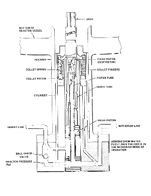 A BWR control rod is scrammed by applying pressure from an accumulator or from the reactor vessel to the volume below the CRD piston and venting the volume above the piston to the scram discharge volume which is near atmospheric pressure. If the insert line is either blocked or broken, a ball check valve built into the CRD (for all BWR/3 and later designs) will admit reactor water to the volume under the piston. (See Figure 80-1.) Thus, the insert line is necessary for scram only when the reactor pressure is low, e.g., during reactor startup.
Breaking the withdraw line will open the volume above the piston to atmospheric pressure and thus cause (not prevent) a scram. The only way to prevent a scram by mechanical damage to the CRD lines is to crimp the withdraw line shut. Breaking or crimping an insert line will prevent a scram only at low reactor pressure at which time the high energy coolant lines, which are to provide the crimping force, are also at low pressure and the reactor is also at very low power. CRD hydraulic lines originate at the CRD flanges. They are routed up from these flanges, curve 90°, and travel horizontally between the CRD housings. The lines are divided into two banks which exit the area under the vessel in two penetrations of the reactor support pedestal placed 180 apart. After traversing the drywell area, the lines exit the containment via two containment penetrations and are then routed to the two banks of hydraulic control units.
In the area under the reactor vessel, there is only one high-energy line, a two-inch lower vessel head drain which is one input to the RWCU system. This line is not considered a significant hazard to the CRD lines for several reasons:
(1) The CRD lines are routed below a set of I-beams. (The CRD housing support is attached to hanger rods which descend from these beams). Thus, the CRD lines are well shielded from the drain line which is above the I-beams.
(2) Breakage of this drain line would be a small LOCA. Normally, the reactor would continue to run, with the only problems being loss of some RWCU flow and a steam-feed flow mismatch. The reactor would not scram until the drywell pressure rose to the scram setpoint. This does not isolate the reactor and main feedwater would continue. Although some rods might fail to insert, and the resulting fission heat would have to be accommodated, the core would not uncover, and there would be no fuel melting.
(3) Even if main feedwater were lost, HPCI has the capacity to handle a 2-inch break (double-ended) with enough extra flow to supply about 40 bundles operating at average power. Again, the core would not uncover.
(4) If HPCI is insufficient, ADS can vent about 38% of rated steam flow. Thus, unless more than 38% of the rods fail to insert, ADS should be able to depressurize the vessel to the point where the high-capacity low pressure ECCS would keep the core flooded.
In any of these small-break scenarios, there would be no fuel melting because the core would not uncover, and there would be no reflood-induced reactivity transient. Depending on the number of control rods that fail to insert, steam production might exceed the turbine bypass capacity, or the MSIVs might close. In such a case, the heat sink provided by the RHR system would likely be insufficient to accommodate the extra heat, and the containment would eventually overpressurize and fail. This would not result directly in a major release of radioactivity, because there would be no severe fuel damage. In theory, the ECCS systems would eventually deplete the suppression pool and the core would eventually uncover. This situation would be alleviated by the fact that, as the suppression pool depletes, the standby liquid control system would become more effective because the concentration of sodium pentaborate in the coolant would increase as coolant boiled off, and fission heat would diminish. Alternatively, the standby coolant supply system could be used to augment the coolant supply.
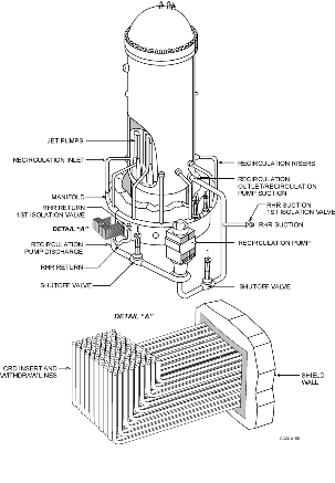
In the area between the reactor support pedestal and the drywell wall, the situation is different. Here, the CRD lines pass near the reactor coolant piping and headers. The recirculation piping exits the vessel from two nozzles located near the bottom of the annulus and travels down through the general area where the CRD lines are located to the recirculation pumps which are at a still lower elevation. Flow from the pumps travels through two pipes up to two semi-circular manifolds, which again are in the general area of the CRD lines. Each manifold then supplies driving flow to the jet pumps through a series of risers, one riser for every two jet pumps. The CRD hydraulic lines cross this area under the manifolds. The usual practice is to route each bank in an array of six horizontal rows of hydraulic lines.
The rest of the vessel piping (feedwater, etc.) is located considerably higher in the drywell. This other piping is not considered a significant hazard because of its distance from the CRD lines and the rather narrow annular gap through which any missiles or jets would have to pass. Thus, concentration was placed on the recirculation piping. Given a break in the recirculation system, an estimate of the probability of crimping or sealing a line completely shut was needed. The best that could be done was to attempt to bound the true probability.
It should be noted that the outcome of the accident under consideration is relatively insensitive to scram timing, so long as the rods are successfully inserted. A small LOCA will not cause a reactor scram until either the water level drops to the scram setpoint or the drywell pressure rises to its setpoint. A large LOCA will depressurize the reactor and stop the fission chain reaction by high voiding of the moderator and the rods need not be inserted until the blowdown is complete. Thus, the interest was in complete rather than partial obstruction of the CRD lines, since partial obstruction would only delay, not prevent, the scram.
No credit was taken for the possibility that non-inserted rods might be widely dispersed and thus may not lead to recriticality. This was not as conservative as it first appeared. The CRD lines are not necessarily routed in such a manner as to disperse the drives they control, and blockage of adjacent lines may well inhibit scram in adjacent CRDs. (Two adjacent control rods can achieve criticality if withdrawn under cold conditions in a BWR.) Finally, insert and withdrawal lines were considered equally, since a large LOCA could depressurize the reactor before a rod with a crimped insert line is completely inserted. (This was in fact quite conservative.) The SLCS is normally capable of borating the moderator to 600 ppm of natural boron (referenced to cold water density) plus a 25% safety margin. This concentration would render the core up to 5% subcritical with all control rods fully removed at cold, xenon-free conditions at the most reactive point in core life. However, following a large LOCA, the SLCS effectiveness is reduced by the diluting effect of the suppression pool, which normally contains about 7½ vessel inventories. Thus, the SLCS can realistically borate only to about 88 ppm. Based on calculations done for ATWS, this would reduce power to roughly 75% of rated (with no rod insertion) but would not shut the reactor down.
Several effects help bring power down.541 First, existing xenon, augmented by xenon increase, holds power down for roughly 24 hours after the accident. Second, the recirculation pumps are no longer providing forced flow through the core, which tends to bring power down by allowing more voiding. Finally, unless the pipe break area is small enough to limit leakage to less than ECCS injection, water level will drop to of the core height, which will greatly reduce moderator density in the upper third of the core. Nevertheless, the core must eventually be brought to cold shutdown by means of the SLCS. Over the long term, this would not be difficult, since more sodium pentaborate mixture could be added to the SLCS so long as the secondary containment remained accessible. It was assumed that the SLCS would be ultimately used to render the core sub-critical over a span of several days.
An examination of the sequence of events was performed. A CRD line can be crimped completely shut by the impact of a missile or energetic fluid jet, if the circumstances are right. First, the line could be caught between the impacting mass and an opposing surface and be flattened shut. Second, if the impact occurred near a point of support for the line, the line could be severed and the stub bent over at a right angle. The line might then be flattened shut at the point of minimum radius of the bend. Finally, a sufficiently energetic impact theoretically could seal the line with only the inertia of the opposite side of the tube providing an opposing force.
In a study of design drawings and field walkdowns of three plants (Browns Ferry 3, Quad Cities 2, and Vermont Yankee) completed as part of the evaluation of Issue 156.6.1, it was found that the break of an RHR return line could also impact the CRD lines, in addition to the recirculation lines. With the exception of BWR/6 plants, the RHR systems in all BWRs are connected to the recirculation system. (In the BWR/6 design, the RHR system returns water to the RCS via a feedwater line or, in LPCI mode, directly into the core bypass region.) The RHR return lines range in size from 16 to 20 inches and connect to, and are unisolatable from, the recirculation lines. Based on rough measurements of MARK I plant drawings, the combined length of the unisolatable portions of the RHR lines (extending out to second isolation valves) was assumed to be 20% of the length of the recirculation lines.
The piping configuration for the three plants reviewed were broken down into two groups, depending on the plant configuration, and the calculations for each group were done separately considering three failure scenarios: pipe whip; fluid jet impingement; and piping fragments.
 : Browns Ferry 3 and Vermont Yankee
Group II: Quad Cities 2
Group II was created to characterize those plants in which a recirculation discharge line was believed to be in very close proximity to one-half of the CRD insert and withdraw lines. (See Figure 80-2.)
Frequency Estimate
Pipe Whip: In this scenario, a recirculation line breaks in such a manner that the whipping pipe strikes one bank of CRD hydraulic lines. It was assumed that the impact would block the entire bank, either by flattening the lines or by breaking the lines and bending them sharply. The CRD lines are located under the two semicircular recirculation manifolds. Thus, they are vulnerable to pipe whip primarily from the manifolds but also from the vertical recirculation pipes carrying flow to and from the recirculation pumps.
The frequency of a large break somewhere in the recirculation system has a mean distribution of 10-4 event/RY. This number was modified to account for several spatial effects, based on the study of design drawings and the system walkdowns mentioned above1811:
- Break Location - Pipe whip restraints are located every 30 around the split manifold, except for two 60 intervals located at the ends of the two semicircles. To be a hazard to the CRD lines, the pipe break must be in the interval which spans the CRD lines. Therefore, a factor of 0.05 was used, which was the length of pipe in one 60 interval divided by the total length of recirculation piping.
- Vertical Piping - The CRD lines may be routed close enough to a recirculation pump suction or discharge line to be affected by breaks in these lines. This was conservatively accounted for by introducing a factor of 2.
- Direction of Whip - The pipe break is as likely to cause the pipe to move sideways or away from the CRD lines as toward them. For this, a factor of 0.25 was assumed.
- Two CRD Line Banks - To account for the fact that there are two sets of lines 180 apart, a factor of 2 was used.
- Extent of Whip - Pipes are not expected to whip more than one pipe diameter at the maximum. In addition, although CRD line routing is done in the field, the fact that insulation has to be installed on recirculation lines gives assurance of at least a foot or so of clearance between the recirculation piping and the CRD lines. The probability that the pipe will whip far enough to hit the CRD lines was assumed to be 0.1.
Multiplying the above numbers, the frequency of the partial (10%) core-melt scenario was estimated to be (10-4)(0.05)(2)(0.25)(2)(0.1) event/RY or 5 x 10⁻⁷ event/RY. (In this and in subsequent calculations, the number of significant figures shown are not intended to imply that the various parameters are known to that accuracy. Instead, the extra figures are given to aid the reader in following the calculations. The uncertainties in these figures will be assessed quantitatively in the "uncertainties and sensitivities" section below.)
When the core is reflooded, about half the core will undergo a cold water reactivity transient. Cladding failure is not a concern here, since it was assumed that every fuel rod in the core would be perforated. Instead, it was necessary to examine the effect of the transient on the fuel matrix itself. The rod drop accident (licensing basis) inserts 1.3% K in about 0.6 seconds. Reflooding the reactor will insert about 8% K, when filled with cold water (with xenon present). However, it takes about 30 seconds to refill the vessel from the bottom to the top of the core. Thus, the reactivity insertion rate is about a factor of eight below that of the rod drop accident and the rod drop accident is more limiting.
The licensing basis calculations for a control rod drop accident predict a peak fuel rod enthalpy of about 220 calories/gram when the inserted reactivity is 1.3% K.540 However, the rod drop accident initial conditions include an initial enthalpy of 20 calories/gram (540F), whereas the cold water reflood transient under consideration here starts with fuel enthalpies as high as 85 calories/gram (2200F). Thus, since the reactivity insertion rate in the reflood transient is less than the reactivity insertion rate in the rod drop accident, the rod drop accident enthalpy increase (H) can be added to the initial enthalpy of the reflood transient and it can be concluded that the peak enthalpy achieved in the reflood transient will be less than 285 calories/gram.
This peak enthalpy corresponds to a point about 20% into the interval between onset of fuel melting (269.4 calories/gram) and complete melting (336.8 calories/gram). Therefore, we will bound the radiological effects of the reflood reactivity transient by assuming that the radioactive release due to this transient is at most 20% of a core-melt release in those fuel bundles where the associated control rods do not scram. Since only half of the control rods fail to scram, the release is bounded by one-half of 20%, or 10% of a full core-melt.
It should be noted that this estimate, which was used in the original analysis, is rather conservative. First, the assumed reactivity insertion rate was about a factor of eight higher than realistic. Second, the H calculations do not take credit for moderator feedback; more realistic calculations have predicted H values on the order of 100 calories/gram.540 Finally, the duration of the hypothetical partially-molten state is very brief. Thus, it is doubtful that the reflood reactivity transient would directly cause this much fuel melting.
However, even if there is less fuel melting caused directly by a reactivity transient when the core is reflooded, it is likely that there will be at least some severe fuel damage in the region where the control rods do not insert. As a shutdown core is reflooded, individual fuel rods, now at a high surface temperature, will first experience film boiling and then "quench" as the cladding temperature drops and the rod transitions into nucleate boiling. However, if the control rods are not inserted, the linear heat generation rate in the fuel rods will greatly increase as the moderator returns and fission heat is generated in addition to decay heat. Even if the fission power is only a few percent of rated power, this would more than double the linear heat generation rate assumed in the ECCS analysis, and it is not likely that cladding temperatures will remain below 2200F.
Finally, it should be noted that the amount of severe fuel damage will change the source term for purposes of calculating man-rem in a Level III PRA analysis. However, it will be shown later that the evaluation of this issue is governed by the Large Early Release Frequency (LERF), where the exact extent of fuel damage is of less importance given that there is at least some fuel melting.
After core reflood, fission power will continue at a low rate in the core.541 The recirculation phase of ECCS may not be sufficient to remove this energy and the containment would then fail due to overpressure. Thus, the radioactivity released by the reactivity excursion would escape to the atmosphere in the manner of a BWR-2 release but with one-tenth its magnitude. In addition, the gap activity from the fuel which did not undergo a reactivity transient, and which would otherwise have been trapped within containment, would be released. There is no BWR release category for this situation, but the consequences of this release can be bounded by those of a PWR-8 release.
With the containment open and steam escaping to the atmosphere, the suppression pool will eventually be depleted of water. If the standby coolant supply system fails (for which a probability of 0.015 was assumed), there would be no liquid water supply for the ECCS and the entire core would melt. For this, a full BWR-2 release was assumed. The frequency for the full core-melt scenario was calculated to be (0.015)(5 x 10⁻⁷) event/RY or 7.5 x 10⁻⁹ event/RY. Theoretically, the partial core-melt frequency should be reduced by a factor of (1 - 0.015), or 0.985, to account for those events that progress to a full core-melt. However, this difference produces an error that is <2% and will be neglected here. (The automated calculations used in the uncertainty studies described below will include this correction.)
Group I Plants: The analysis for the recirculation lines was expanded to include the RHR lines with the following assumptions: (1) the large-break LOCA frequency for the recirculation system is 10-4 event/RY; (2) the ratio of the unisolatable portion of the RHR piping length to the total RHR/recirculation piping length is 0.2; (3) only about one-third (0.33) of the RHR length of piping is near the CRD lines; (2) pipe whip may be towards or away from the CRD line bundle (or sideways), so that the probability of motion towards the bundle is 0.25; (3) the probability that a pipe would whip far enough to contact a CRD line bundle is 0.1; and (4) the scenario results in a 10% core-melt. Combining the result for the recirculation system from above, the frequency of a partial (10%) core-melt is given by the sum of 5 x 10⁻⁷ event/RY (from the recirculation line break) and (10-4)(0.2)(0.33)(0.25)(0.1) event/RY (from the RHR line break). The result is a frequency estimate of or 6.6 x 10⁻⁷ event/RY.
Again, if the standby coolant supply system is assumed to fail (for which a probability of 0.015 was assumed), there would be no liquid water supply for the ECCS and the entire core will melt. For this, a full BWR-2 release was assumed. The frequency of the full core-melt scenario was calculated to be 7.5 x 10⁻⁹ event/RY + (0.015)(1.6 x 10⁻⁷) event/RY or 10-8 event/RY.
Group II Plants: The analysis for the recirculation lines was expanded to include the RHR lines with the following assumptions: (1) the CDF increase for RHR piping is the same as calculated for Group I plants (1.6 x 10⁻⁷ event/RY); (2) the frequency of a recirculation line break is the same (10-4 event/RY); (3) there is an additional contribution to CDF resulting from the recirculation piping being in close proximity to the CRD bundles; (4) the probability is 0.05 that, given a recirculation line pipe break, the break would be in the discharge line sector; (5) because pipe whip may be towards or parallel to the CRD line bundles that straddle it, there is a probability of 0.5 that the motion will be towards the bundles; (6) the probability that a pipe would whip far enough to contact a CRD line bundle is 1; and (7) the scenario results in a 10% core-melt. Therefore, the frequency of a partial (10%) core-melt is given by the sum of 5 x 10⁻⁷ event/RY (from the recirculation line break), 1.6 x 10⁻⁷ event/RY (from the RHR line break), and (10-4)(0.05)(0.5)(1) event/RY (from the recirculation lines in close proximity). This results in a frequency estimate of 3.16 x 10⁻⁶ event/RY.
Again, if the standby coolant supply system is assumed to fail (for which a probability of 0.015 was assumed), there would be no liquid water supply for the ECCS and the entire core will melt. For this, a full BWR-2 release was assumed. The frequency of the full core-melt scenario was calculated to be 7.5 x 10⁻⁹ event/RY + (0.015)(3.16 x 10⁻⁶ ) event/RY or 4.74 x 10⁻⁸ event/RY.
Fluid Jet Impingement: A fluid jet driven by a 1000 psi pressure cannot directly flatten a tube which contains 1000 psi fluid. However, impingement of such a jet will cause severe vibration of CRD lines. The lines may flatten as they repeatedly hit each other or hit any other structures (e.g., supports) which are within their vibrational amplitude. In reality, one would expect these lines to be more likely to rupture than to flatten. Nevertheless, flattening is possible and was assumed here.
The hazard to the CRD lines depends on their arrangement and distance from the pipe break. A typical practice in routing CRD hydraulic lines is to arrange the lines in six horizontal rows. In such an arrangement, lines located within the matrix would be shielded from some of the force of an external fluid jet. Thus, if the CRD lines are located close to the pipe break, the jet would be concentrated and might penetrate into the CRD lines matrix with sufficient force to cause vibratory flattening. Conversely, if the lines are located at some distance from the break, the jet would be more diffuse and less likely to penetrate past the first row of lines but will also, because of this same dispersion, impinge on a wider area and thus affect more of the outside row.
It was assumed that the break (and the jet) are 22-inches in diameter, which is the diameter of the recirculation manifold. (This is based on judgment. It is possible, of course, for the jet area to be any size from near zero to the equivalent of two pipe diameters, if the break is circumferential. If the break is longitudinal, the length of the break could theoretically extend the length of the manifold. A jet of one pipe diameter seems a reasonable first assumption.) To cover both the near and far cases, it was assumed that the entire top row of lines is flattened and, in addition, a 22-inch (transverse) span is flattened to a depth of all six rows. For a 1000 MWe plant with 185 control rods, this means that 43 rods would fail to insert; this corresponds to 23% of the core.
The above was based on the assumption that the CRD lines are arranged in a matrix 6 rows high and with a pitch of two inches. In such a case, the matrix would be 62 inches wide. The probability of a break in the recirculation manifold being above this span is about 1.7%.
The event tree is similar to that of a pipe whip: a recirculation line breaks (10-4/RY), the break is above the CRD lines (0.017), and the fluid jet is directed downward (0.25). The result is that 23% of the core would experience a reactivity transient and continued steam production would eventually rupture the containment (20% of a BWR-2 release in the uncontrolled fuel plus a PWR-8 release). However, priority parameters calculated from these figures must be doubled to account for the presence of two banks of CRD lines and doubled again to account for the presence of vertical recirculation piping. Thus, the frequency of a partial or 4.6% core-melt (20% of 23%) was estimated to be (10-4) (0.017)(2)(2)(0.25) event/RY or 1.7 x 10⁻⁶ event/RY.
If the standby coolant supply system is assumed to fail (0.015), the ECCS would eventually run out of water and the entire core would melt (BWR-2 release). The frequency for this full core-melt scenario was calculated to be (0.015)(1.7 x 10⁻⁶) event/RY or 2.55 x 10⁻⁸ event/RY.
Group I Plants: The analysis for the recirculation lines was expanded to include the RHR lines with the following assumptions: (1) the large-break LOCA frequency for the recirculation system is 10-4 event/RY; (2) the ratio of the unisolatable portion of the RHR piping length to the total RHR/recirculation piping length is 0.2; (3) only about one-third (0.33) of the RHR length of piping is near the CRD lines; (4) the probability that the jet direction is towards the CRD lines is 0.1; and (5) the scenario would result in a 4.6% core-melt. Combining the result for the recirculation system from above, the frequency of a partial (4.6%) core-melt was estimated to be 1.7 x 10⁻⁶ event/RY + (10-4)(0.2)(0.33)(0.1) event/RY or 2.36 x 10⁻⁶ event/RY.
If the standby coolant supply system is assumed to fail (0.015), the ECCS would eventually run out of water and the entire core would melt (BWR-2 release). The frequency for this full core-melt scenario was calculated to be 2.55 x 10⁻⁸ event/RY + (0.015)(2.36 x 10⁻⁶) event/RY) or 3.54 x 10⁻⁸ event/RY.
Group II Plants: The analysis for the recirculation lines was expanded to include the RHR lines with the following assumptions: (1) the core-melt frequency increase for RHR piping and recirculation line breaks are the same as calculated for Group I (6.6 x 10⁻⁷ event/RY), plus other additions; (2) the probability is 0.05 that, given a recirculation line break, the break would be in the discharge line sector; (3) the portion of the recirculation discharge line directly adjacent to the CRD bundle is 0.5; (4) the probability is 0.5 that the jet direction is towards the CRD lines; and (5) the scenario would result in a 4.6% core-melt. Therefore, the frequency of a partial (4.6%) core-melt is given by 1.7 x 10⁻⁶ event/RY + 6.6 x 10⁻⁷ event/RY + (10-4)(0.05)(0.5)(0.5) event/RY or 3.61 x 10⁻⁶ event/RY.
If the standby coolant supply system is assumed to fail (0.015), the ECCS would eventually run out of water and the entire core will melt (BWR-2 release). The frequency for this full core-melt scenario was calculated to be 2.55 x 10⁻⁸ event/RY + (0.015)(1.91 x 10⁻⁶) event/RY or 5.41 x 10⁻⁸ event/RY.
Pipe Fragments: The original analysis included the effects of pipe fragments on the CRD lines. Based on the additional insights gained during the evaluation of Issue 156.6.1, the failure modes of large reactor coolant piping were thermal fatigue or intergranular stress corrosion cracking which generally occurred in the region of circumferential welds. This suggested that clean breaks with the production of fragments is almost impossible. For the sake of completeness, the effect of pipe fragments will be discussed, but these sequences will not be included in the final analysis.
The hazard from pipe fragments is different from that of a fluid jet. First, because a solid object can concentrate its impact in a small area, it can block a CRD line directly by denting the line. Second, solid objects will retain this full impact over a great distance, as opposed to the diffusion of a fluid jet. On the other hand, a solid object cannot flatten a CRD line within the matrix without breaking the lines in the rows above.
The original analysis assumed that a section of recirculation manifold with a span equal to a pipe diameter (22 inches) suddenly breaks into fragments. To estimate the number of CRD lines which could be dented shut, it was further assumed that the lines are located immediately adjacent to the manifold. The pipe fragments, which at close range would act like one solid mass, would then impact a 22-inch span of the top row of CRD lines. Since these lines may well be all withdrawal lines, it was assumed that eleven control rods would fail to insert.
The accident sequence starts out with a large LOCA (10-4/RY). The break must be over the CRD lines (0.017) and pointed down (0.25). The result is that 6% of the core would return to criticality after a mild reactivity excursion (20% of a BWR-2 release per fuel bundle) and the containment eventually would be overpressurized (75,000 man-rem from gap activity). This equates to a 1.2% partial core-melt. Again, the resultant figures must be multiplied by four to account for vertical pipes and two CRD banks. The frequency of this partial (1.2%) core-melt scenario is (10-4)(0.017)(0.25)(2)(2) event/RY or 1.7 x 10⁻⁶ event/RY.
If the standby coolant supply system is assumed to fail (0.015), the entire core would melt (BWR-2 release). The frequency for this full core-melt scenario was calculated to be (0.015)(1.7 x 10⁻⁶) event/RY or 2.55 x 10⁻⁸ event/RY. Once again, these sequences are shown in Table 80-1 for comparison purposes only and were not included in the final analysis.
Table 80-1
Core-Melt Frequency Summary Group Iand Group II Plants
| FAILURE MODE | GROUP I | GROUP II | ||
|---|---|---|---|---|
| Partial Core-Melt (Event/RY) | Full Core-Melt (Event/RY) | Partial Core-Melt (Event/RY) | Full Core-Melt (Event/RY) | |
| Pipe Whip | 6.60 x 10⁻⁷ | 1.00 x 10⁻⁸ | 3.16 x 10⁻⁶ | 4.74 x 10⁻⁸ |
| Fluid Jet Impingement | 2.36 x 10⁻⁶ | 3.54 x 10⁻⁸ | 3.61 x 10⁻⁶ | 5.41 x 10⁻⁸ |
| Pipe Fragments | [Not included] | [Not included] | [Not included] | [Not included] |
| TOTAL: | 3.0 x 10⁻⁶ | 4.5 x 10⁻⁸ | 6.8 x 10⁻⁶ | 1.0 x 10⁻⁷ |
Other Considerations
Uncertainties and Sensitivities: Many of the parameters involved in the estimates above are not "standard" PRA unavailabilities and, thus, do not have a commonly accepted distribution with mean estimates and error bounds. Nevertheless, an uncertainty analysis was performed although, in the absence of better numbers, the following judgment was used to estimate error bounds in some parameters:
| Initiating event - large break LOCA | The "classic" distribution from NUREG-11501081 was used - a lognormal distribution, mean of 10-4/RY, with a lognormal error factor of 10 |
| Standby coolant supply unavailability | A lognormal distribution with an error factor of 10 was used, based on NUREG-1150,1081 but using a mean from the original analysis. The effect of this will be examined in the sensitivity studies below. |
| Direction, including direction of whip and direction of fluid jet | Depending on whether the pipe is within or outside of the CRD tube array, these parameters were either 50% or 25%. Based mostly on judgment (but partly on some piping diagrams), a normal distribution was used, with the 5th and 95th percentile limits set at ±0.2. Thus, the limits were at 0.30 to 0.80 and 0.05 to 0.45, respectively. |
| Geometric factors, including the likelihood of a break being located above the CRD lines, or being between the two supports that bracket the CRD lines | In the original analysis, these parameters are based on a length of vulnerable circular manifold divided by the total length of primary system piping. This quotient was then multiplied by a factor of two (for two CRD banks) and another factor of two to account for an assumed equal length of vulnerable piping in the vertical runs. Since modern automated event tree analysis requires split fractions that are less than or equal to unity, the two factors of two were combined with the original quotient into just one parameter. Because this is still basically a ratio of lengths of pipe, the uncertainty distribution was assumed to be normal (rather than lognormal), centered on the point estimate in the analysis. For error bounds, the 5th and 95th percentiles were set at zero and at double the point estimate, based purely on judgment. |
| Extent of pipe whip | The analysis assumed a likelihood of 0.1 of the CRD lines being impacted by a whipping pipe. For this parameter, an exponential distribution with mean of 0.1 was used. |
| RHR fraction | This is the ratio of unisolable RHR piping to the total length of primary system piping. The original analysis estimated 0.2 for this parameter. For the uncertainty analysis, a normal distribution was used, with the 5th and 95th percentile limits set at 0.1 and 0.3, based on judgment. |
| RHR piping location | This is the fraction of RHR piping which is located near the CRD bundles, for the Group I plants. The analysis described above estimated this parameter to be 0.33. For the uncertainty analysis, a normal distribution was assumed, with the 5th and 95th percentile bounds set at zero and 0.66. |
| Fraction of recirculation piping located within the CRD bundles | This is the fractional length of piping located physically within the CRD bundles, for Group II plants. The analysis above used 0.05 (i.e., 5%). For the uncertainty analysis, a normal distribution was assumed, with the 5th and 95th percentile bounds set at 0.02 and 0.08. |
The uncertainty analysis was constructed based on the above parameters, and distributions were calculated for the partial and full core-melt frequencies using 10,000 samples. For the original analysis, the results are shown in Table 80-2. Again, as the ranges in the Table 80-2 clearly indicate, the number of significant figures shown are not intended to imply that these results have high uncertainty, but instead are provided to assist the reader in following the calculations.
Table 80-2
Core-Melt Frequency (Event/RY) Uncertainties Original Analysis
| Event | End State | Point Estimate | Mean | 5th percentile | 95th percentile | Median |
|---|---|---|---|---|---|---|
| Fluid jet | 4.7% core-melt | 1.7E-6 | 1.8E-6 | 2.8E-8 | 7.0E-6 | 5.3E-7 |
| Full core-melt | 2.6E-8 | 2.6E-8 | 7.1E-11 | 1.0E-7 | <1.0E-8 | |
| Fragmentation | 1.2% core-melt | 1.7E-6 | 1.8E-6 | 2.8E-8 | 7.0E-6 | 5.3E-7 |
| Full core-melt | 2.6E-8 | 2.6E-8 | <1.0E-8 | 1.0E-7 | <1.0E-8 | |
| Pipe whip | 10% core-melt | 4.9E-7 | 4.9E-7 | <1.0E-8 | 2.0E-6 | 8.8E-8 |
| Full core-melt | <1.0E-8 | <1.0E-8 | <1.0E-8 | 2.5E-8 | <1.0E-8 |
As can be seen, the means are not significantly higher than the point estimates. The distributions are not symmetric, as can be seen by how far the medians differ from the means. This is not surprising considering that the initiating event and the standby coolant supply unavailability are assumed to have log-normal distributions, but the geometric and directional parameters are assumed to have linear normal distributions. Moreover, some of the parameters were assigned 5th percentile bounds at zero, which "chops off" the lower 5% of the distribution and tends to lower the tail of the distributions of the products. Starting with the original analysis, a series of changes and sensitivities were performed, the first of which was the removal of the contribution of fragmentation. The results are shown in Table 80-3.
Table 80-3
Core-Melt Frequencies (Event/RY) Original Analysis With and Without Fragmentation Contribution
| End State | Point Estimate | Mean | 5th percentile | 95th percentile | Median | |
|---|---|---|---|---|---|---|
| Original analysis | 1.2% | 1.7E-6 | 1.8E-6 | 2.8E-8 | 7.0E-6 | 5.3E-7 |
| 4.7% | 1.7E-6 | 1.7E-6 | 2.6E-8 | 7.0E-6 | 5.1E-7 | |
| 10% | 5.0E-7 | 5.3E-7 | <1.0E-8 | 2.1E-6 | 8.7E-8 | |
| Full | 5.8E-8 | 6.6E-8 | <1.0E-8 | 2.3E-7 | 7.0E-7 | |
| Original analysis (no fragmentation) | 4.7% | 1.7E-6 | 1.7E-6 | 2.5E-8 | 7.0E-6 | 5.1E-7 |
| 10% | 5.0E-7 | 5.3E-7 | <1.0E-8 | 2.1E-6 | 8.7E-8 | |
| Full | 3.3E-8 | 3.7E-8 | <1.0E-8 | 1.3E-7 | <1.0E-8 |
Here, the various states are summed by end state, and the "full core-melt " rows are the sums of the contributions of the pipe whip, fragmentation, and fluid jet scenarios. Although the point estimates for the full core-melt states are the sums of the individual full core-melt frequencies from the fluid jet, fragmentation, and pipe whip event trees, the means and limits are the result of adding up the three sequences 10,000 times while varying the initiating event frequency and split fractions about their distributions, and then forming a distribution for the sum. Using the original analysis with the fragmentation contribution removed as a base, the sequences were modified to cover the Group I and Group II plants. The results are shown in Table 80-4.
As can be seen from an examination of Table 80-4, the means do not vary significantly from the point estimates. In addition to the calculations described in Table 80-4, two sensitivity studies were performed. The first was to examine possible double-counting of the vertical runs of RHR and recirculation piping. In the original analysis, the fraction of primary system piping physically located such that a break could threaten the CRD hydraulic lines was estimated by examining the layout of the split manifold, and then doubling the result to account for vertical piping runs for which no layout information was available. This is, in effect, an assumption that a vertical run of either RHR or recirculation piping, equal in length to the length of threatening pipe in the split manifold, is located close enough to pose a hazard to the CRD lines. This is a reasonable estimate for most plants, if no other information is available. However, the analysis of the Group I and II plants added vertical piping contributions to the original analysis. For Group II plants especially, if the analysis has added the contributions of vertical pipes known to be right in the middle of the CRD line bundles, it is known with equal certainty that these vertical pipes are not located in any other nearby location, and the original accounting for vertical piping runs should be removed.
Table 80-4
Core-Melt Frequency (Event/RY) Uncertainties Original Analysis, Group I Plants, and Group II plants
| End State | Point Estimate | Mean | 5th percentile | 95th percentile | Median | |
|---|---|---|---|---|---|---|
| Original analysis, no fragmentation | 4.7% | 1.7E-6 | 1.7E-6 | 2.5E-8 | 7.0E-6 | 5.1E-7 |
| 10% | 5.0E-7 | 5.3E-7 | 1.9E-9 | 2.1E-6 | 8.7E-8 | |
| Full | 3.3E-8 | 3.7E-8 | <1.0E-8 | 1.3E-7 | <1.0E-8 | |
| Group I plants | 4.7% | 2.3E-6 | 2.4E-6 | 6.1E-8 | 9.4E-6 | 8.0E-7 |
| 10% | 6.5E-7 | 7.0E-7 | <1.0E-8 | 2.8E-6 | 1.2E-7 | |
| Full | 4.5E-8 | 5.2E-8 | <1.0E-8 | 1.8E-7 | <1.0E-8 | |
| Group II plants | 4.7% | 4.7E-6 | 4.7E-6 | 1.5E-7 | 1.8E-5 | 1.7E-6 |
| 10% | 3.1E-6 | 3.1E-6 | 9.2E-8 | 1.2E-5 | 1.0E-6 | |
| Full | 1.2E-7 | 1.3E-7 | <1.0E-8 | 4.7E-7 | 1.7E-8 |
The second sensitivity has to do with the availability of the standby coolant supply. This is not a stand-alone system. Although individual plants vary, every modern BWR has some means of pumping water from the ultimate heat sink into the reactor if the suppression pool is not available. Typically, this is done by providing a valved-out link between RHR service water and the RHR suction lines. Use of standby coolant supply requires a number of manual actions on the part of the operator. The original analysis for this issue used an unavailability for standby coolant supply of 1.5%, based on WASH-140016-era analyses. The NUREG-11501081 Peach Bottom PRA performed a much more extensive analysis of the equipment and actions associated with standby coolant supply, and calculated a much higher unavailability (a mean of about 17%). For this screening analysis, the effect of increasing the unavailability of standby coolant supply is not to change the likelihood of an accident, but instead to change the end state from a partial core-melt to a full core-melt. The results of the two sensitivities are shown in Table 80-5.
As can be seen from Table 80-5, removing the double-counting of vertical piping reduces the various core damage frequencies by about 20%, and an updated treatment of standby coolant supply increases the full core-melt frequency by an order of magnitude. This last sensitivity calculation, with the double-counting removed and the updated standby coolant supply, is the "best" estimate for this generic issue for the Group II plants - the most vulnerable group.
Containment Response: In any of these scenarios, even if the entire core is not damaged, the reactor core is not subcritical, and fission heat production continues. The RHR system is sized to remove decay heat. (For example, the Browns Ferry RHR has four heat exchangers rated at 70 million BTU/ hour each, which corresponds to about 2.5% of the reactor's rated thermal power of 3293 MW - equivalent to decay heat about 10 minutes after shutdown.) Obviously, if fission heat production continues with 23% of the rods failing to insert (as in the fluid jet scenario), and the standby liquid control system unable to shut the reactor down, the RHR system will not be able to accommodate the extra heat and the containment will overpressurize. Thus, any of these end states, even those involving partial core damage, will result in containment failure and a large early release.
Table 80-5
Core-Melt Frequency (Event/RY) Sensitivity Studies
| End State | Point Estimate | Mean | 5th percentile | 95th percentile | Median | |
|---|---|---|---|---|---|---|
| Group II plants | 4.7% | 4.7E-6 | 4.7E-6 | 1.5E-7 | 1.8E-5 | 1.7E-6 |
| 10% | 3.1E-6 | 3.1E-6 | 9.2E-8 | 1.2E-5 | 1.0E-6 | |
| Full | 1.2E-7 | 1.3E-7 | <1.0E-8 | 4.7E-7 | 1.7E-8 | |
| Group II plants (original vertical pipe contribution removed) | 4.7% | 3.9E-6 | 3.9E-6 | 1.3E-7 | 1.4E-5 | 1.4E-6 |
| 10% | 2.9E-6 | 2.8E-6 | 8.3E-8 | 1.1E-5 | 9.3E-7 | |
| Full | 1.0E-7 | 1.1E-7 | <1.0E-8 | 4.0E-7 | 1.4E-8 | |
| Group II plants (no extra vertical pipe, modern standby coolant supply unavailability) | 4.7% | 3.3E-6 | 3.1E-6 | 9.3E-8 | 1.2E-5 | 1.1E-6 |
| 10% | 2.4E-6 | 2.3E-6 | 5.8E-8 | 8.9E-6 | 7.3E-7 | |
| Full | 1.2E-6 | 1.6E-6 | 2.3E-8 | 6.3E-6 | 4.4E-7 |
Another perspective regarding containment response can be gained by examining the suppression pool inventory. Again, using the Browns Ferry plant as an example, the suppression pool inventory is 135,000 ft3 (maximum), which is about 8.4 million pounds of water. Normal feedwater flow at full power is about 13.4 million pounds per hour. If fission power were to continue at about 10% of rated due to rods failing to scram, the entire suppression pool inventory would be boiled off in about 6.3 hours (not including the existing reactor water inventory, nor including the effect of residual heat removal, both of which would stretch the time somewhat).
End States: The end states in this screening analysis, i.e., 1.2%, 4.7%, 10% and 100% core-melt, are subject to considerable uncertainty. These numbers would be of significance if this calculation were carried out to PRA Level III consequences (e.g., man-rem/RY), as was done in the original analysis. However, a screening decision can be made based on LERF and thus the uncertainty in the degree of core damage was not explored.
Large Early Release Frequency (LERF): An uncertainty study was also performed for the LERFs for the various scenarios. The results are shown in Table 80-6.
It should be noted that some of these large early releases are much larger than others, since the total LERF includes sequences that breach containment, but only melt a small part of the reactor core. Nevertheless, the numbers are significant in that any increase in LERF greater than 10-6/RY passes the screening tests documented in Figure C4 of the NRC Management Directive 6.4 Handbook.
It should also be noted that, for the specific case of Group II plants and using the NUREG-11501081 unavailabilities for standby coolant supply, the full core damage frequency is 1.2 x 10⁻⁶ event/RY, and all of these sequences lead to containment overpressurization and failure.
Table 80-6
Large Early Release Frequencies (Event/RY)
| Point Estimate | Mean | 5th Percentile | 95th Percentile | Median | |
|---|---|---|---|---|---|
| Plants with Original Analysis Piping Configuration (no fragmentation) | 2.2E-6 | 2.4E-6 | 4.9E-8 | 9.5E-6 | 7.7E-7 |
| Group I Plants | 3.0E-6 | 3.3E-6 | 8.7E-8 | 1.3E-5 | 1.1E-6 |
| Group II Plants | 6.8E-6 | 7.0E-6 | 2.2E-7 | 2.6E-5 | 2.6E-6 |
Basic Assumptions: There are several mechanistic or phenomenological postulates in the analysis that were not addressed in the uncertainty analysis because they were postulated to be true by the generic issue itself. Like an importance measure calculation, screening of a generic issue assumes these to be true, and then attempts to estimate their risk significance. Nevertheless, the task action plan for the issue should include an investigation of the validity of the following assumptions.
Can a whipping pipe or other moving mass crush a CRD line completely shut? A CRD line pressurized to 1000 psi will resist denting. It is straightforward to show that the imposed force must be at least 1500 pounds per linear inch just to overcome the internal pressure, with no credit for the stiffness of the stainless steel tube wall, and assuming that the tube is in contact with a stationary support on the opposite side from the impacting mass.
A fluid jet driven by 1000 psi cannot directly flatten a tube filled with 1000 psi fluid. The analysis assumes that the CRD lines will strike each other when exposed to the jet, and will flatten by repeated impacts.
If a CRD line were crimped shut, would the internal fluid pressure be sufficient to overcome the stiffness of the stainless steel and partially re-open the tube, to the point where the associated control rod would eventually be inserted?
The pipe whip analysis for the Group II plants assumes that the whipping pipe will bend the much-smaller CRD hydraulic lines to the point where the small lines will develop "kinks" which will close off all flow. The configuration of the CRD lines is such that the lines have a 90-degree bend or elbow near the point of impact, and are not likely to have significant lateral support - the impacting large pipe can bend the smaller lines without stretching them. Experience suggests that this failure mode is quite credible, but the rather large number of CRD lines may add up to a significant resistive force, even though the individual lines may be relatively weak. An investigation of the force needed to "kink" a significant number of lines would be of considerable interest.
An investigation of these assumptions, either by calculation or by experiment, could add significant confidence to the resolution of the issue.
Early BWR Designs: As was described earlier, the control rod drive mechanism for all BWR/3 and later designs incorporates a ball check valve which prevents a broken insert line from interfering with a scram. There are still two operating plants, both of the BWR/2 product line, for which this may not be true. However, the BWR/2 design uses an ECCS for large-break LOCAs which is based on a high volume core spray - the core is not re-flooded after a large line break located below the level of the core. Thus, the accident scenarios associated with the issue do not apply to the BWR/2 design.
Old vs. New Analysis: An obvious question is, why has the conclusion changed from the original analysis? This is in spite of the fact that the pipe fragmentation sequences have been removed. An examination of the table will show two reasons. First and most obvious, the more vulnerable piping configurations in the Group I and Group II plants were not known when the original analysis was performed in 1984. These piping configurations are obviously of greater concern.
A second reason is more subtle. When the original analysis was performed, the generic issue screening criteria were based only on either core damage frequency or man-rem/RY. In 2002, a new set of criteria were added which were based on LERF. This particular generic issue involves a partial core-melt, and thus a relatively low source term and low public risk, but a high likelihood of containment failure, because only a small amount of fission heat will overwhelm the capacity of the RHR heat exchangers. Thus, the LERF criterion becomes limiting.
CONCLUSION
Applying the criteria of NRC Management Directive 6.4, Figure C4, the potential changes in the large early release frequencies (ΔLERF) placed the issue in the category where work on a technical assessment was pursued.1809This conclusion was corroborated by the consideration of uncertainties in the analysis.
Scram motion in a BWR CRD is affected by admitting the pressure in the scram accumulator to the area below the drive piston, and venting the area above the piston to the scram discharge volume, which is at atmospheric pressure. The CRDs are equipped with a ball check valve, which will admit reactor water below the drive piston if the inlet line pressure falls below reactor pressure. Thus, neither crimping nor breaking the insert line will prevent a scram when the reactor is at power. By contrast, crimping the withdrawal line shut would inhibit a scram; however, breaking the withdrawal line (thereby venting it to atmospheric pressure) will cause the drive to scram. Since the piping is expected to fail open before it is crimped closed, the control rods will scram using reactor pressure. Therefore, this issue was closed with no changes to existing regulations or guidance.1868
REFERENCES
|