Resolution of Generic Safety Issues: Issue 10: Surveillance and Maintenance of Tip Isolation Valves and Squib Charges ( NUREG-0933, Main Report with Supplements 1–35 )
DESCRIPTION
Historical Background
This issue apparently originated as a DOR proposal and was discussed in SECY-80-325.8 The issue as previously evaluated196 is whether periodic replacement of the squib charges and circuit checks of the traveling in-core probe (TIP) guide tube explosive shear valves should be included in the Technical Specifications of each BWR plant, similar to the requirements for the explosive valves in the standby liquid control system (SLCS). In this updated evaluation, the necessity for periodic inspection of the ball valve and the shear valve squib charge are addressed.
Safety Significance
The TIP system is used to calibrate the neutron monitoring system. The system consists of the neutron detector attached to a flexible drive cable which is driven by a gear box assembly located outside of the primary containment. The flexible cable and attached neutron detector is inserted into the reactor core through stainless steel tubing (TIP guide tubes). An indexing mechanism which is located inside the primary containment allows the use of a single TIP in any of 10 different guide tube paths. Each reactor has 4 or 5 TIP systems, depending on core size.
Each TIP system has a ball valve and cable shearing valve in the guide tubing external to the containment penetration. These valves, which are the subject of this report, ensure containment integrity in the event of a rupture of the guide tube at a location inside the reactor vessel.
The ball valve which is normally closed opens only when the TIP is being inserted. On an isolation signal (manual or high drywell pressure), the TIP cable retracts and the ball valve closes. If the TIP fails to retract or the ball valve fails to close, a keylock switch can be activated to fire the explosive squib on the shear valve and crimp the guide tube shut. The controls for the TIP systems, which include valve position indicating lights and the squib keylock switches, are located in the control room.
The safety significance of the TIP isolation valves is that if the guide tube ruptures and both valves fail open, the reactor coolant would be provided with a direct path from the reactor vessel to the reactor building. Thus, primary containment could be breached and radioactivity released. This scenario, however, requires certain sequences of events and multiple failures of components which are discussed below.
Sequence 1: During LPRM calibration or flux mapping, the TIP is inserted into the reactor, a leak develops in the TIP tube, the TIP does not retract, and the squib-shear valve fails.
Sequence 2: During normal operation with the TIP withdrawn, a TIP tube leaks, the failed TIP is aligned with the containment penetration, the ball valve fails, and the squib-shear valve fails.
Sequence 3: During core calibration an accident leading to core-melt occurs. All the TIP tubes in the reactor fail. In one case the TIP is inserted and the cable prevents the ball valve from closing. In the second case the TIP is not inserted but the ball valve fails. In both cases the squib-shear valve fails.
Possible Solutions
A possible solution implied by the DOR request is to require surveillance and maintenance on the TIP isolation valves. The surveillance and maintenance requirements would thus provide greater assurance that the isolation valves would function when called upon to operate.
The Standard Technical Specifications (STS) for General Electric Boiling Water Reactors,66 Section 3/4.6.3, Primary Containment Isolation Valves (PCIS), requires surveillance of the TIP system ball and shear valves. In the case of the ball valves, the typical monthly LPRM calibration requirements in accordance with Table 4.3.1-1 of the STS for GE BWRs66 exercises the valves more often than the STS explicitly require for surveillance of the ball valves.
In the case of the squib-shear valves, the STS Specification66 4.0.5 requires inservice testing per Section XI of the ASME Code and Addenda.14 Whether the plant is using STS or plant-specific Technical Specifications, inservice testing, as a minimum, should follow the ASME Section XI14 requirements unless exceptions are approved (Section 50.55a, 10 CFR Part 50197). A proposed Revision 4 to the STS is being prepared, such that testing requirements for the squibs in the TIP shear valves would parallel the testing requirements of the squib charges in the SLCS.
PRIORITY DETERMINATION
Frequency Estimate
(1) TIP Tube Failures
Data from "Nuclear Power Experience"105 indicate that 10 TIP tubes have failed with 180 reactor-years of operating experience. Assuming 50 tubes per reactor gives a failure rate of:

This does not include the TIP failures that occurred at the Kou Sheng reactor in Taiwan in 1982. These failures were due to use of the LPCI during cooldown, which is a rarely used alternate cooling mode and only applicable to BWR/5 and BWR/6 reactors. GE is providing a design change that will prevent this failure mode in the future. Therefore, this failure is not representative of future failures.
(2) TIP Tube Alignment
TIP guide tube alignment through the index mechanism is needed to provide the leakage path from the vessel to the isolation valves. The probability that the failed guide tube will be in one of the five indexed groups is 0.2. Since there are 10 guide tube inputs to one index output, the conditional probability of a failed tube being aligned through any one indexer to the isolation valves is:

(3) TIP Insertion Frequency
The TIP is inserted in each tube for about 5 minutes each month. This gives a probability of a tube containing a TIP at any given time of:
![]()
(4) Ball Valve Failure Frequency
Prior to 1976, ball valve failures in the TIP isolation systems were frequent. Since 1976 redesign of the ball valve actuator has improved
the reliability of these valves. Based on information reported in "Nuclear Power Experience,"105 there have been 16 TIP isolation (ball valve) failures from January 1976 to January 1982. Assuming five valves per reactor, this yields a ball valve failure rate over 128 reactor years of 2.5 x 10⁻² per valve-year. Since these valves are exercised at least once a month during LPRM calibration, the probability that any ball valve will be inoperable at any given time is:

(5) Squib Failure Frequency
"Nuclear Power Experience"105 reported inoperative conditions for squib charges in both TIP and SLCS systems in four plants in operation during the 1970 to 1982 time interval. The inoperative conditions were from loose connectors, inadequate installation, blown fuses, and inadequate primer charges which failed all of the squib valves in the systems. It is indicated from the above information that the squib-shear valve failures have been common mode type failures which have been dominated by conditions other than the detonation reliability of the squib charge. Because a single squib charge in a reactor with five TIP machines could
be in-place for up to 10 years14 and because of the absence of requirements for circuit checks of the squib-shear valves, we will conservatively assume a common mode failure for the squib-shear valves with a probability of failure of:
![]()
(6) Accident Frequency
It is assumed that all TIP tubes fail in the event of a core-melt. Also assuming 12 hours to calibrate all LPRMs each month in each reactor yields a probability of being in a calibration (Pc) mode at any given time of 1.6 x 10⁻². Since it is assumed that all TIP tubes fail (PTF = 1.0) per core-melt, the probability of tube alignment is eliminated in this proposed sequence.
From WASH-1400,16 the BWR release category representative of core-melt and no containment rupture is a Category 4 release. The probability of core-melt for a Category 4 release is:
![]()
The frequency of radioactive release resulting from the sequences described above is:
Sequence 1
Sequence 2 (for each indexer)

Since there are five indexers,
![]()

Sequence 3

Sequence 1 and Sequence 2 are calculated to have approximately the same chance of occurring. However, because of the TIP blockage within the coolant path, the coolant release to the reactor building for Sequence 1 would be approximately 20% of the release for Sequence 2. Sequence 3a has three times the probability of Sequence 3b, but the leak rate in Sequence 3b is a factor of 5 higher.
Consequence Estimate
Sequence 2: The reactor vessel coolant leak through the TIP guide is conservatively assumed as 10 gpm. Assuming 4 x 10⁻⁶ Ci/gal activity (Section 3/4 4-5, STS66), and 1 week to shut down the plant and stop the leak, the radioactivity release is only 218 Ci. This release is into a subcompartment in the secondary containment.
The SGTS consists of demisters, high-efficiency particulate filters, and activated-charcoal filters and is designed to clean the secondary containment atmosphere and exhaust through the stack. Thus, the consequence of any radioactivity release for Sequence 2 is insignificant when compared to Sequence 3 below.
Sequence 3: The fraction of core inventory released from a BWR Category 4 release is 10-3 (WASH-140016 - Table VI.2-1). The total core inventory is 5 x 10⁹ Ci (WASH-140016 - Table VI.3-1). In the WASH-140016 calculations, the Category 4 release is based on the assumption that a hole larger than 1-inch in diameter is required to preclude containment rupture under core melt conditions. The release in Sequence 3b is assumed to be 0.1 of a Category 4 release, which is the ratio of the area provided by a failed TIP guide tube to a 1-inch diameter hole. This conservative approximation yields a release of 5 x 10⁵ Ci. The risk associated with this Sequence 3 release is, therefore, 5 x 10⁻³ Ci/RY.
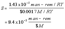
The worst case consequence is Sequence 3 which is estimated to result in the release of 5 x 10⁵ Ci at a frequency of 10-8/RY. The public dose is estimated to be similar to a BWR-4 release (2.1 x 10⁸ Ci or 602,000 man-rem). Therefore, the total risk reduction is (5 x 10⁵)(10-8)(602,000/2.1 x 108) man-rem/RY or 1.43 x 10⁻⁵ man-rem/RY.
Cost Estimate
We assume that the utilities are currently firing and replacing at least one squib charge per refueling in accordance with ASME Section XI14 requirements. For a plant with five TIP machines, we will assume two additional squibs are fired and replaced per refueling outage (per year). The cost of the squibs is estimated to be $50 per squib. The time required to fire and replace a squib is assumed to be 4 hours. We also assume an added requirement to verify the continuity of the explosive squib charges at least once per month. The additional estimated plant costs (Cu), including a one-time licensing fee amortized over 20 years and a manpower cost of $100,000/man-yr is given by

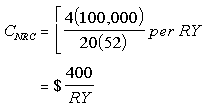
The NRC cost (4 man-weeks) to revise the Technical Specifications, amortized over 20 years, is approximately:

This results in a total annual cost of $1,700/RY or $0.0017M/RY.
Value/Impact Assessment
Based on the risk reduction per RY and cost estimates given above, the value/ impact score is given by:

Other Considerations
If a TIP tube leaks and the isolation valves fail, a costly decontamination problem could result. Based on the minimal cost to provide maintenance and surveillance to assure reliability of these valves, it would seem prudent for the utilities to improve on the current procedures. However, this event presents no significant radiological hazard or risk to the public and no effort to develop regulatory requirements is warranted.
CONCLUSION
Based on the above value/impact assessment, this issue should be DROPPED from further consideration.
REFERENCES
|


